Close
0%
0%

Motion Controller

An update to "not GRBL" but using an ISR.

Similar projects worth following
This is an update to "Not GRBL" but this time using an Interupt Service Routine (ISR).
I have dropped the acceleration ramp (more trouble than it is worth) so you have to stay within the stepper motor pull-in limits. Otherwise the code is simpler and better!
I also go to some effort to step through the software consruction steps.

G-Code and Motion Control (AKA GRBL)

You don't actually need a G-Code interpreter to use motion control on your project, at least to start. It can be added later. A "Better Turret" is an example of motion control without G-Code (https://hackaday.io/project/28478-a-better-turret):
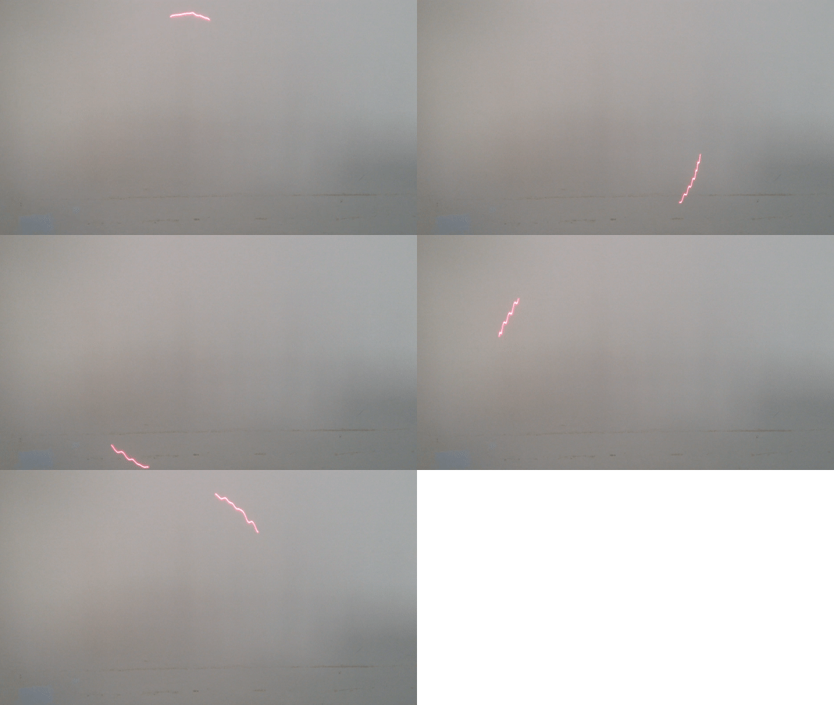

With this in mind here are the steps in building my motion controller:

  1. The Interrupt Service Routine (ISR)
  2. Bressenham's 3D line algorithm
  3. Adding a command buffer
  4. Adding flow control
  5. Adding a Serial Interface (not G-Code)
  6. Implementing a G-Code interpreter

GCodeMotionControllerSerial.ino

Requires review and testing!

x-arduino - 12.87 kB - 07/14/2018 at 11:45

Download

Adobe Portable Document Format - 162.79 kB - 01/14/2018 at 03:33

Preview
Download

x-csrc - 2.54 kB - 01/14/2018 at 03:32

Download

x-arduino - 1.41 kB - 01/14/2018 at 02:59

Download

  • After A Long Break

    agp.cooper07/14/2018 at 08:53 0 comments

    Getting Back Up To Speed

    It appears as though the code is waiting to be testing. It has been a long time so I need to review what I have written.

    Serial Initialisation

    The initialisation of the serial interface is always tricky with the Arduino, here is my code:

      // Indicate ready
      Serial.begin(9600);
      while (!Serial);
      Serial.println("Motion Control V1.0");
      Serial.flush();

    The first line is pretty standard and for this application I don't want to go any faster than 9600 baud. The motion controller is pretty processor intensive so not a great idea to sent data too quickly.

    The second line is almost essential on Linux PCs (no so much on Windows PCs). Without this line the first serial print is often (i.e. always) garbled. Basically the code has to wait until the Serial system is ready. On Windows PCs a 200 ms wait seems to work better.

    The function of flush() as changed over time but at the moment it just waits until the output has been sent. It has no function on the input. In the past I would calculate the required delay for the text length to ensure that the serial has been sent before continuing. Why wait? If you send too much data and overflow the buffer then data will be lost.

    For "gCodeSender" the ready message needs to be modifed to something like:

    Serial.println("Grbl v0.1a");

    Flow Control

    In "Not GRBL" I used software handshakes (i.e. XON/XOFF) as I could only process one command at a time. With a ring buffer I should be able to use the "ok" protocol.

    The variable "okay" is incremented upon completion of the motion (in the motion control ISR):

            ...
            steps--;
            if (steps==0) okay++;
            ...

    and decremented each time it is printed to the serial port (in the main loop):

    void loop()
    {
      // Flow control
      if (okay>0) {
        Serial.println("ok");
        cli();okay--;sei();
      }
    }

    Serial Event

    I am using serialEvent() to decode the gCode and save the "primative" comands to the ring buffer. It is fairly complicated:

    • Clean up the command string
    • Decode the motion commands
    • Push motion commands onto stack (not checked if the stack is full)
    • Decode immediate commands
    void serialEvent()
    {
      // Rember between calls
      static long xNext=0;
      static long yNext=0;
      static long zNext=0;
      static long fNext=Feed;
      // Reset upon each call
      long mNext=-1;
      bool set=false;
      long fQuery;
      long xQuery;
      long yQuery;
      long zQuery;
      long nQuery;
      char inData[63];
      int bRead;
    
      // Get command string
      bRead=Serial.readBytesUntil('\n',inData,63);
      if (bRead>1) {
        bRead--;
        inData[bRead]='\0'; // End of string
        
        // Clean up command string
        for (int i=0;i<bRead;i++) {
          // To upper case
          if ((inData[i]>='a')&&(inData[i]<='z')) inData[i]-=32;
          if ((inData[i]>='0')&&(inData[i]<='9')) {
            // Integer numbers
          } else if (inData[i]=='-') {
            // Sign
          } else if (inData[i]=='.') {
            // Decimal
          } else if (inData[i]=='?') {
            // Ready
          } else if (inData[i]=='X') {
            // X axis movement
          } else if (inData[i]=='Y') {
            // Y axis movement
          } else if (inData[i]=='Z') {
            // Z axis movement
          } else if (inData[i]=='F') {
            // Feed rate
          } else if (inData[i]=='M') {
            // M Code
          } else if (inData[i]=='$') {
            // Status
          } else if (inData[i]=='!') {
            // Pause
          } else if (inData[i]=='~') {
            // Resume
          } else if (inData[i]=='@') {
            // Set current position as origin
          } else {
            // Clear character
            inData[i]=' ';
          }
        }
        
        // Decode motion commands
        for (int i=0;i<bRead;i++) {
          if (inData[i]=='X') {
            xNext=(long)(atof(inData+i+1)*xStepsPerMM);
            set=true;
          } else if (inData[i]=='Y') {
            yNext=(long)(atof(inData+i+1)*yStepsPerMM);
            set=true;
          } else if (inData[i]=='Z') {
            zNext=(long)(atof(inData+i+1)*zStepsPerMM);
            set=true;
          } else if (inData[i]=='F') {
            fNext=atol(inData+i+1);
            if (fNext<1) fNext=1;
            if (fNext>4095) fNext=4095;
            set=true;
          } else if (inData[i]=='M') {
            mNext=atol(inData+i+1);
            set=true;      
          }
        }
        // Push motion commands onto stack (no check if full)
        if (set) {
          // Push must not be interrupted
          cli();
          // Psuedo M-Codes
          if ((mNext==2)||(mNext==...
    Read more »

  • Adding a Motion Command Queue

    agp.cooper01/14/2018 at 05:43 0 comments

    Adding a Motion Command Queue

    A motion command queue is a very useful addition for motion contol. It allows new motion commands to decoded and queued while a previous motion command is being executed. This minimises delays between motion commands. This is really important for clean laser burns.

    A queue is just a buffer with two pointers "head" and "tail". The head points to the next available buffer position and tail points to the next motion command to be executed. If the head pointer equals the tail pointer then the queue is empty. The queue "wraps" around when it get to the end of the buffer.

    Here is a "push" example:

      // Queue length
      queue=head-tail;
      if (queue<0) queue=queue+QueueSize;
      if (queue<QueueSize-1) {
        // Push motion command
        cli();
        xNew[head]=iSin[cosAngle];
        yNew[head]=iSin[sinAngle];
        zNew[head]=0;
        .
        .
        .
        if (++head>=QueueSize) head=head-QueueSize;
        sei();
      }

    What does it do:

    1. Checks the queue has room for a new command.
    2. Disables interrupts (no interupts while updating volatile variables!).
    3. Sets the values to the head of the queue.
    4. Updates the head pointer and check if it has to be rolled over.

    Here is a "pop" example (inside the ISR)

      if (head!=tail) {
        // Determine next motion
        dx=xNew[tail]-xCurrent;
        dy=yNew[tail]-yCurrent;
        dz=zNew[tail]-zCurrent;
        .
        .
        .
        // Pop queue
        if (++tail>=QueueSize) tail=tail-QueueSize;
      }
    

    What does it do:

    1. Checks that the queue is not empty.
    2. Gets the values from the tail of the queue.
    3. Updates the tail pointer and checks if it has to be rolled over.

    Motion Flow Control

    By quering the queue length, the flow of motion commands can be managed.

    "GCodeSender" does this by expecting an "ok" from the last sent command before sending the next command.

    The motion controller code checks if it has room on the queue before returning an "ok" to the last motion command. It is best to keep a couple of queue slots free for compound commands like M30 (e.g. "End of program"). As M30 could be interpreted as:

    1. Turn off laser or lift head to safe height.
    2. Go to Home position.

    Here is the update motion controller code:

    /*
      Simple 3 Axis ISR Motion Controller - Part 3: Add a queue
      =========================================================
      Written by Alan Cooper (agp.cooper@gmail.com)
      This work is licensed under the
      Creative Commons Attribution - Non Commercial 2.5 License.
      This means you are free to copy and share the code (but not to sell it).
    
      Motion is in absolute steps
      Feed rate range is 1 to 4095 steps per second
    */
    
    // Motor controller (CNC board) pin mapping: 
    #define DirX           2
    #define DirY           3
    #define DirZ           4
    #define StepX          5
    #define StepY          6
    #define StepZ          7
    #define Enable         8        // Enable stepper motors (active low)
    #define Laser         12        // Turn laser on or off
    
    // Motion controller defaults
    #define Feed        1000        // Default feed rate
    #define QueueSize     16        // Queue size
    #define xReverse   false        // Reverse X axis direction
    #define yReverse    true        // Reverse Y axis direction
    #define zReverse   false        // Reverse Z axis direction
    
    // Motion controller queue and ISR variables
    volatile int head=0;            // Queue pointer (head)
    volatile int tail=0;            // Queue pointer (tail)
    volatile int queue=0;           // Queue length
    volatile long xNew[QueueSize];  // The target X co-ordinate
    volatile long yNew[QueueSize];  // The target Y co-ordinate
    volatile long zNew[QueueSize];  // The target Z co-ordinate
    volatile long feed[QueueSize];  // Set motion feed rate
    volatile long laser[QueueSize]; // Laser (on/off)
    volatile long xCurrent=0;       // The current X co-ordinate
    volatile long yCurrent=0;       // The current Y co-ordinate
    volatile long zCurrent=0;       // The current Z co-ordinate
    volatile long steps=0;          // Number of steps remaining in motion
    ISR(TIMER2_OVF_vect)
    {
      static long dx,dy,dz;
      static long ax,ay,az;
      static long sx,sy,sz;
      static long mx,my,mz;
      static long stepX,stepY,stepZ;
      static unsigned int phase=0;
      static unsigned int magic=8000;
      if (phase<0x8000) {
        phase+=magic;
        if (phase>=0x8000) {
          if (steps==...
    Read more »

  • Adding 3D Line to the ISR

    agp.cooper01/14/2018 at 05:06 0 comments

    Adding 3D Line to the ISR

    Okay, it get complicated quickly but this is really only the beginning!

    /*
      Simple 3 Axis ISR Motion Controller - Part 2: Add Motion Control 
      ================================================================
      Written by Alan Cooper (agp.cooper@gmail.com)
      This work is licensed under the
      Creative Commons Attribution - NonCommercial 2.5 License.
      This means you are free to copy and share the code (but not to sell it).
    
      Motion is in absolute steps
      Feed rate range is 1 to 4095 steps per second
    */
    
    // Motor controller (CNC board) pin mapping: 
    #define DirX           2
    #define DirY           3
    #define DirZ           4
    #define StepX          5
    #define StepY          6
    #define StepZ          7
    #define Enable         8        // Enable stepper motors (active low)
    #define Laser         12        // Turn laser on or off
    
    // Motion controller defaults
    #define Feed        1000        // Default feed rate
    #define xReverse   false        // Reverse X axis direction
    #define yReverse    true        // Reverse Y axis direction
    #define zReverse   false        // Reverse Z axis direction
    
    // Motion controller and ISR variables
    volatile int xNew;  // The target X co-ordinate
    volatile int yNew;  // The target Y co-ordinate
    volatile int zNew;  // The target Z co-ordinate
    volatile int feed;  // Set motion feed rate
    volatile int laser; // Laser (on/off)
    volatile int xCurrent=0;       // The current X co-ordinate
    volatile int yCurrent=0;       // The current Y co-ordinate
    volatile int zCurrent=0;       // The current Z co-ordinate
    volatile int steps=-1;         // Number of steps remaining in motion
    ISR(TIMER2_OVF_vect)
    {
      static int dx,dy,dz;
      static int ax,ay,az;
      static int sx,sy,sz;
      static int mx,my,mz;
      static int stepX,stepY,stepZ;
      static unsigned int phase=0;
      static unsigned int magic=8000;
      if (phase<0x8000) {
        phase+=magic;
        if (phase>=0x8000) {
          if (steps==0) {
            // Determine next movement parameters
            dx=xNew-xCurrent;
            dy=yNew-yCurrent;
            dz=zNew-zCurrent;
            ax=abs(dx);
            ay=abs(dy);
            az=abs(dz);
            sx=xNew<xCurrent?-1:xNew>xCurrent?1:0;
            sy=yNew<yCurrent?-1:yNew>yCurrent?1:0;
            sz=zNew<zCurrent?-1:zNew>zCurrent?1:0;
            if ((ax>=ay)&&(ax>=az)) {
              mx=0;
              my=ay-(ax>>1);
              mz=az-(ax>>1);
              steps=ax;
            } else if ((ay>=ax)&&(ay>=az)) {
              mx=ax-(ay>>1);
              my=0;
              mz=az-(ay>>1);
              steps=ay;
            } else {
              mx=ax-(az>>1);
              my=ay-(az>>1);
              mz=0;
              steps=az;
            }
            // Set the stepper directions
            if (xReverse) {
              digitalWrite(DirX,(1-sx)>>1);
            } else {
              digitalWrite(DirX,(sx+1)>>1);
            } 
            if (yReverse) {
              digitalWrite(DirY,(1-sy)>>1);
            } else {
              digitalWrite(DirY,(sy+1)>>1);
            }
            if (zReverse) {
              digitalWrite(DirZ,(1-sz)>>1);
            } else {
              digitalWrite(DirZ,(sz+1)>>1);
            }
            // Set laser
            if (laser>0) {
              digitalWrite(Laser,HIGH);
            } else {
              digitalWrite(Laser,LOW);
            }
            // Set feed
            magic=feed<<3;
          }
          // Reset step low
          digitalWrite(StepX,LOW);
          digitalWrite(StepY,LOW);
          digitalWrite(StepZ,LOW);
        }
      } else {
        phase+=magic;
        if (phase<0x8000) {
          if (steps>0) {
            // Advance steppers (25us)
            stepX=0;
            stepY=0;
            stepZ=0;
            if ((ax>=ay)&&(ax>=az)) {
              if (my>=0) {
                my-=ax;
                stepY=sy;
              }
              if (mz>=0) {
                mz-=ax;
                stepZ=sz;
              }
              my+=ay;
              mz+=az;
              stepX=sx;
            } else if ((ay>=ax)&&(ay>=az)) {
              if (mx>=0) {
                mx-=ay;
                stepX=sx;
              }
              if (mz>=0) {
                mz-=ay;
                stepZ=sz;
              }
              mx+=ax;
              mz+=az;
              stepY=sy;
            } else {
              if (mx>=0) {
                mx-=az;
                stepX=sx;
              }
              if (my>=0) {
                my-=az;
                stepY=sy;
              }
              mx+=ax;
              my+=ay;
              stepZ=sz;
            }
            xCurrent+=stepX;
            yCurrent+=stepY;
            zCurrent+=stepZ;      
            // Step HIGH
            if (stepX!=0) digitalWrite(StepX,HIGH);
            if (stepY!=0) digitalWrite(StepY,HIGH);
            if (stepZ!=0) digitalWrite(StepZ,HIGH);
            steps--;
            // Set steps to indicate new motion not set
            if (steps==0) steps=-1;
          }
        }
      }
    }
    
    int iSin[360];
    void setup()
    {
      // LED
      pinMode(LED_BUILTIN,OUTPUT);
    
      // Initialise Motor Controller Hardware
      pinMode(DirX,OUTPUT);
      pinMode(StepX,OUTPUT);
      pinMode(DirY,OUTPUT);
      pinMode(StepY,OUTPUT);
      pinMode(DirZ,OUTPUT);
      pinMode(StepZ,OUTPUT);
      pinMode(Enable,OUTPUT);
      pinMode(Laser,OUTPUT);
      digitalWrite(DirX,LOW);
      digitalWrite(StepX,LOW);
      digitalWrite(DirY,LOW);
      digitalWrite(StepY,LOW);
      digitalWrite(DirZ,LOW);
     digitalWrite(StepZ,LOW);
    ...
    Read more »

  • Bressenham's Line Algorithm

    agp.cooper01/14/2018 at 03:32 0 comments

    Bressenham's Line Algorithm

    Best to have a look at https://en.wikipedia.org/wiki/Bresenham%27s_line_algorithm for details of Bressenham's line algorithm. My version is just an optimised version of that code.

    Testing the Code

    Here is some test code for my version of Bressenham's line algorithm:

    /*
      3D Bresenham's algorithm
      ========================
      Written by Alan Cooper (agp.cooper@gmail.com)
      This work is licensed under the
      Creative Commons Attribution - NonCommercial 2.5 License.
      This means you are free to copy and share the code (but not to sell it).
    
      Original Bressenham algorithm source:
      https://en.wikipedia.org/wiki/Bresenham%27s_line_algorithm
    */
    // Include libraries
    #include <stdio.h>
    #include <stdlib.h>
    #include <string.h>
    #include <math.h>
    #include <stdbool.h>
    #include "/usr/include/graphics.h"
    // Other Linker Options: -lXbgi -lX11 -lm
    
    void line3d(int xOld,int yOld,int zOld,int xNew,int yNew,int zNew) {
      int i,n;
      int dx,dy,dz;
      int ax,ay,az;
      int sx,sy,sz;
      int mx,my,mz;
      int xStep,yStep,zStep;
    
      dx=xNew-xOld;
      dy=yNew-yOld;
      dz=zNew-zOld;
      ax=abs(dx);
      ay=abs(dy);
      az=abs(dz);
      // Sign function
      sx=dx<0?-1:dx>0?1:0;
      sy=dy<0?-1:dy>0?1:0;
      sz=dz<0?-1:dz>0?1:0;
      if ((ax>=ay)&&(ax>=az)) {
        mx=0;
        my=ay-(ax>>1);
        mz=az-(ax>>1);
        n=ax;
      } else if ((ay>=ax)&&(ay>=az)) {
        mx=ax-(ay>>1);
        my=0;
        mz=az-(ay>>1);
        n=ay;
      } else {
        mx=ax-(az>>1);
        my=ay-(az>>1);
        mz=0;
        n=az;
      }
    
      for (i=1;i<=n;i++) {
        xStep=0;
        yStep=0;
        zStep=0;
        if ((ax>=ay)&&(ax>=az)) {
          if (my>=0) {
            my-=ax;
            yStep=sy;
          }
          if (mz>=0) {
            mz-=ax;
            zStep=sz;
          }
          my+=ay;
          mz+=az;
          xStep=sx;
        } else if ((ay>=ax)&&(ay>=az)) {
          if (mx>=0) {
            mx-=ay;
            xStep=sx;
          }
          if (mz>=0) {
            mz-=ay;
            zStep=sz;
          }
          mx+=ax;
          mz+=az;
          yStep=sy;
        } else {
          if (mx>=0) {
            mx-=az;
            xStep=sx;
          }
          if (my>=0) {
            my-=az;
            yStep=sy;
          }
          mx+=ax;
          my+=ay;
          zStep=sz;
        }
        putpixel(xOld,yOld,BLACK);
        xOld+=xStep;
        yOld+=yStep;
        zOld+=zStep;
        putpixel(xOld,yOld,BLACK);
      }
    }
    
    int main(void)
    {
      // Display results
      initwindow(900,700);
      setbkcolor(WHITE);
      cleardevice();
      setcolor(BLACK);
      setlinestyle(SOLID_LINE,EMPTY_FILL,NORM_WIDTH);
      setfillstyle(SOLID_FILL,WHITE);
    
      // Units are pixels
      setcolor(RED);
      line(200,700-100,600,700-100);
      line(600,700-100,600,700-500);
      line(600,700-500,200,700-500);
      line(200,700-500,200,700-100);
      setcolor(BLACK);
    
      // Overlay my version on line
      line3d(200,700-100,0,600,700-100,0);
      line3d(600,700-100,0,600,700-500,0);
      line3d(600,700-500,0,200,700-500,0);
      line3d(200,700-500,0,200,700-100,0);
    
      printf("Done - Enter to exit");
      getchar();
      closegraph();
    
      return(0);
    }
    

    The program first draws a box in RED using the Xbgi line() routine and then over-draws with my Line3d() routine in BLACK. If no RED shows then tat means it works. I have actually done a lot more testing than this!

    To compile  the code (under linux) you need to install the Xbgi library and add to your "Other Linker Options":

    -lXbgi -lX11 -lm

    The BGI graphics library is also available for Windows (but it is not 100% compatible) but I leave you to find and install it.

    I have added  "xbgi-quickref.pdf" to my files area.

    AlanX

  • The Interrupt Service Routine

    agp.cooper01/14/2018 at 02:49 0 comments

    The Interrupt Service Routine (ISR)

    The core of motion control is the frequency generator ISR. Here is an ISR "Blink" sketch:

    /*
      Simple 3 Axis ISR Motion Controller - Part 1: The ISR Frequency Generator 
      =========================================================================
      Written by Alan Cooper (agp.cooper@gmail.com)
      This work is licensed under the 
      Creative Commons Attribution - NonCommercial 2.4 License.
      This means you are free to copy and share the code (but not to sell it).
    */
    
    volatile unsigned int magic=0;
    ISR(TIMER2_OVF_vect)
    {
      static unsigned int phase=0;
      if (phase<0x8000) {
        phase+=magic;
        if (phase>=0x8000) {
          digitalWrite(LED_BUILTIN,LOW);  // LED on
        }
      } else {
        phase+=magic;
        if (phase<0x8000) {
          digitalWrite(LED_BUILTIN,HIGH); // LED off
        }
      }
    }
    
    void setup()
    {
      // LED
      pinMode(LED_BUILTIN,OUTPUT);
      
      // Use Timer 2 for ISR
      // Good for ATmega48A/PA/88A/PA/168A/PA/328/P
      cli();
      TIMSK2=0;                                     // Clear timer interrupts
      TCCR2A=(0<<COM2A0)|(0<<COM2B0)|(3<<WGM20);    // Fast PWM
      TCCR2B=(1<<WGM22)|(2<<CS20);                  // 2 MHz clock and (Mode 7)
      OCR2A=243;                                    // Set for 8197 Hz
      OCR2B=121;                                    // Not used
      TIMSK2=(1<<TOIE2)|(0<<OCIE2A)|(0<<OCIE2B);    // Set interrupts
      sei();
    
      // Update frequency without interrupt
      unsigned int freq=1;                          // Note freq should be between 1 and 4095
       
      cli();
      magic=(freq<<3); 
      sei();
    }
    
    void loop()
    {
    
    } 
    

    The code is based on my Midi project (https://hackaday.io/project/27429-simple-concurrent-tones-for-the-arduino).

    The heart of the frequency generator are two 16 bit unsigned integers "magic" and "phase". Now, magic is added to phase approximately 8192 times a second. If magic equal 8, then phase will overflow and reset every second (i.e. 65536=8x8192). I can not set the ISR for exactly 8192 Hz but 8197 Hz is close enough. The ISR sets the LED on as it passes 0x7FFF and reset the LED as it passes 0xFFFF. The formula for magic is "=freq*8", and the range for freq is 1 to 4095 Hz. 

    If you upload the sketch to an UNO or a Nano the LED will flash at 1 Hz, assuming "freq=1".

    AlanX

View all 5 project logs

Enjoy this project?

Share

Discussions

Similar Projects

Does this project spark your interest?

Become a member to follow this project and never miss any updates