 DatanoiseTV
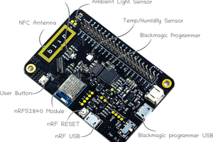
Initially the sensor nodes were using the RF24 and RF24Network only. The current version uses the ChibiOS Real-Time Operating System and the "Narcoleptic" library to put the ATMega328P into deep-sleep when not transmitting and to allow multi-tasking.
0%
0%
Cumulus Wireless Sensor Platform
The wireless customizable low-cost home automation solution
Become a Hackaday.io member
Already have an account? Log in.
Just one more thing
To make the experience fit your profile, pick a username and tell us what interests you.
Pick an awesome username
hackaday.io/
Your profile's URL: hackaday.io/username. Max 25 alphanumeric characters.
Pick a few interests
Projects that share your interests
People that share your interests


 Mahesh Venkitachalam
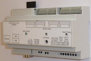
 Florian Cliquet
 Nathann
 Juan Albanell
By August 20th you must have the following:
- A video. It should be less than 2 minutes long describing your project. Put it on YouTube (or Youku), and add a link to it on your project page. This is done by editing your project (edit link is at the top of your project page) and adding it as an "External Link"
- At least 4 Project Logs
- A system design document
- Links to code repositories, and remember to mention any licenses or permissions needed for your project. For example, if you are using software libraries you need to document that information.
You should also try to highlight how your project is 'Connected' and 'Open' in the details and video.
There are a couple of tutorial video's with more info here: http://hackaday.com/2014/07/26/4-minutes-to-entry/
Good luck!