Over the Xmas week I assembled a couple of these boards - and had a number of problems. The biggest problem was trying to solder the Silicon Labs Si3402 802.3af PD and integrated switcher. This is a cool chip as it combines the dual rectifier bridges, TVS suppressor, the PD manager and an integrated switcher with included MOSFET. All other PD solutions required a lot of extra components which adds to the expense and board real estate. 2 problems with this chip, the QFN profile is a real pain to hand solder and I had literally 10 attempts to try to get it right, with a combination of hand soldering, using a sandwich toaster (heater on top and bottom) as well as a makeshift hot air gun using a paint stripper gun with alfoil on the nozzle to direct the hot air to the chip. All these methods worked to some degree, and I learnt how to time the solder melt to emulate wave soldering but the biggest problem was getting the chip aligned as it was so small. The pads on the board I used should have been a little bigger to make the soldering easier, and I finally got it working with a combination of hot air soldering and hand soldering afterwards. This particular QFN did not have much metal exposed on the side of the chip so hand soldering was really tough, so pre-tinning both the chip and the board was needed, and using a small screwdriver to force the chip down onto the board to make good joins on all pins when using hot air soldering was needed, and amount of pre-tinning had to not too little (won't make a joint) or too much (creating a bridge on the underside of the chip). Solder paste would have been easier.... So when these boards were fired up and didn't work I wasn't sure it was the soldering, the board or the design. Unlikely to be the design as I pretty much kept to the data sheet and application note, and validated it against a 3rd party schematic for a similar design (Olimex PoE board). I triple checked my schematic in Kicad and the board and apart from a couple of small changes that should not have mattered I was sure everything was OK. When the board powered up, it performed the 802.3 classification, started up the switcher but then the switcher shut down and cycled through the startup sequence again. Not being able to see the quality of the soldering under the QFN chip I pretty much blamed the soldering for the problem so re-did the chip many times (the hot air gun was perfect for desoldering). By the 10th try I thought I'd re-read the data sheet / app note to see if I was missing anything, re-checked the component values etc. and found a short sentence in the middle of the datasheet that said in some situations the switcher will cycle if there is a small load present. I had actually used a small dummy load (100 ohms resistor on the output) as the Olimex design had this, however it wasn't enough especially as I hadn't soldered the PIC yet (wanting to see that the PoE output voltages were OK first) and when I dropped this to 50, voila the board fired up and stable. I had spent literally a couple of days on this and getting quite frustrated so was pretty happy to see it working, and validating that the design and board were OK! If that last change didn't work I was about to redo the boards with another PD chip.
The second problem for me was that due to restricted board space I was using the non-isolated design so the output earth was referenced to 48v - 3.3v and once I had the PIC soldered up I fired up for the first time the PICkit 3 programmer and plugged it into my PC, then into the programming header on the board. The PICkit has a translucent case and I could literally see fireworks inside the case and the familiar smell of burning silicon. Both the PIC and the programmer were toast - this time I knew exactly what the problem was, as I had problems with my USB oscilloscope earlier when trying to debug the PD chip for the same reason. In use it won't be a problem as the sensors will only be connected to Ethernet, but as the PoE voltages are so high, these types of mistakes when prototyping are fatal to the components. Luckily the programmers are cheap ($15 from China) but I have to wait for a new one now. While I was at it I also ordered a new USB oscilloscope with USB isolation (OWON - with much better software than my old SDO-2100 from Hantek that doesn't run on Windows 8....).
So I still don't have a running prototype but am confident I can get it to work now once I get the new programmer. There ended up only 1 mistake with the design and the boards, I had the Ethernet bias resistor for the PIC connected to the wrong pin (my fault not the board). A little bit of surgery on the board will fix that. I'm looking forward to playing with the TCP/IP stack on the PIC, and looking at RTOS options for the firmware, or I might recycle a PIC firmware framework I wrote a little while back that was a simple RTOS for the 16F series. I have 2 uses for these modules at the moment, one is for a ultrasonic water tank sensor, another is for a doorbell which will have video (using the OV7670 FIFO sensor which I got for $10) and 2 way audio which will be a good challenge and the hardware should be capable enough. This module will likely end up as the back end of a relay board for controlling other things, and I will write a HTTP REST API for it as well for easy control and integration into my DIY home automation system.
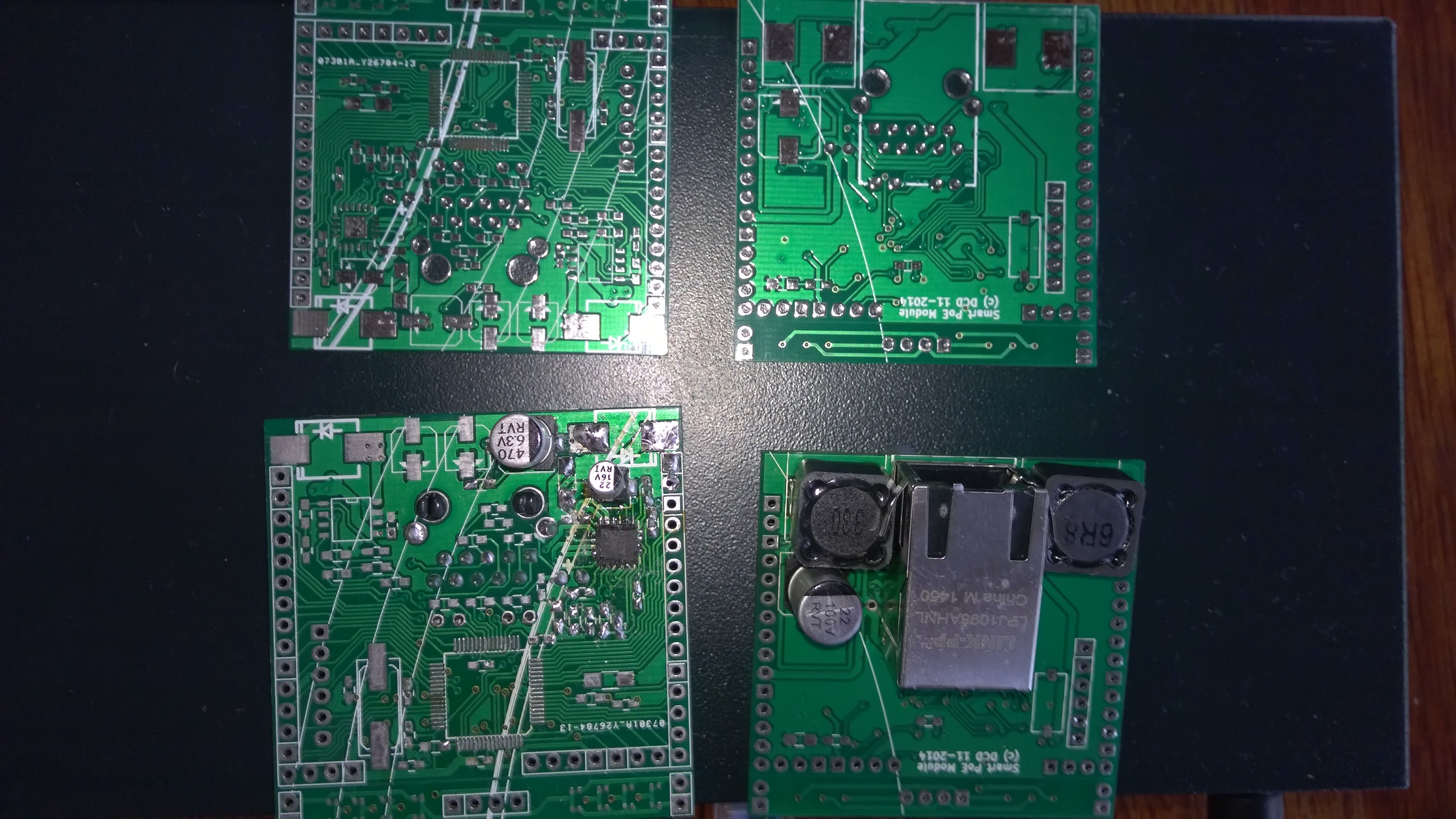
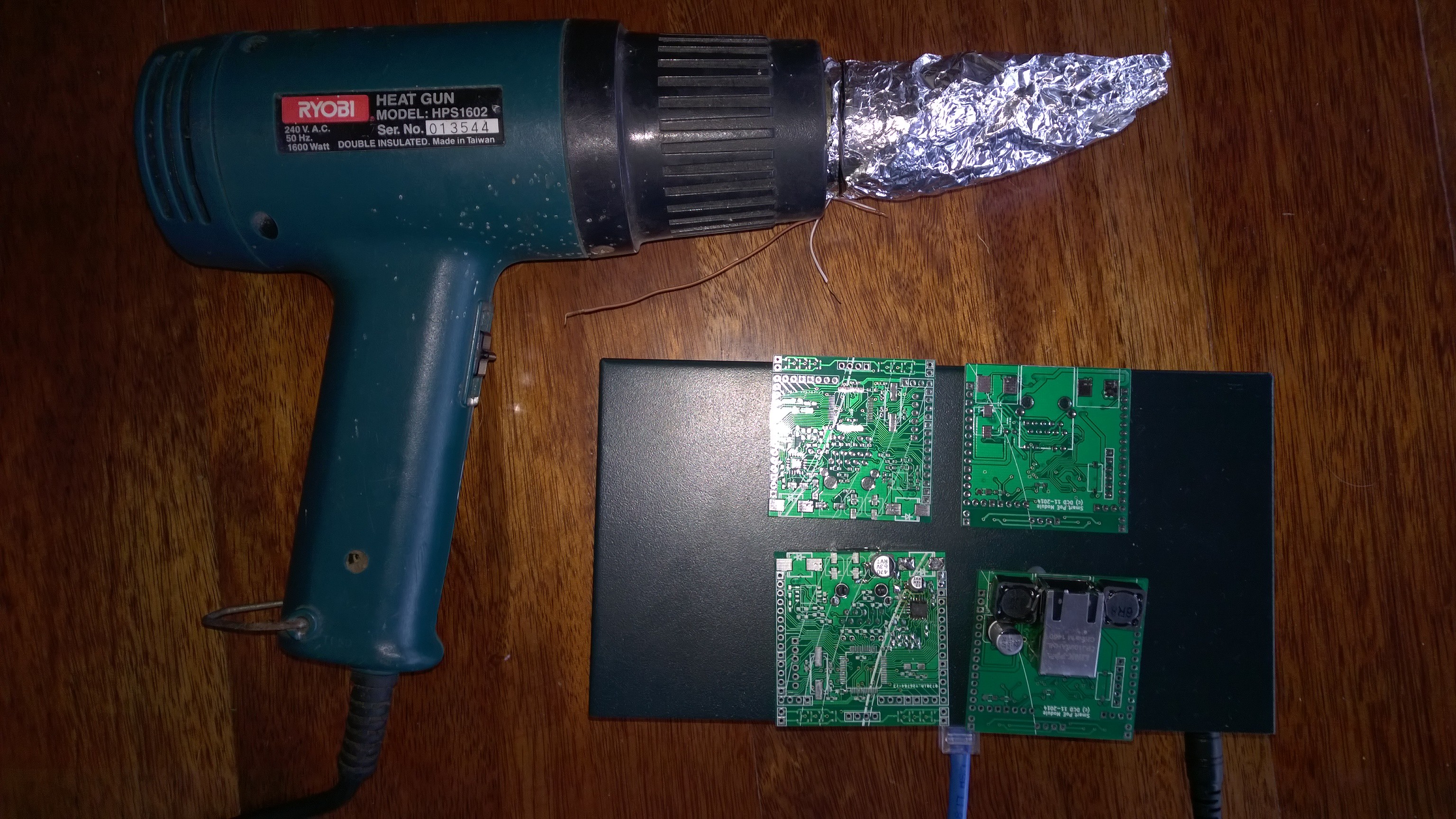 Above is the modified paint stripper hotgun (which looks hacky but very effective) and the boards sitting on the PoE switch I got off AliExpress for $70 (and well worth it, it took a beating with testing the PD modules).
Sorry for the long post, I should have provided shorter updates over the last month. Stay tuned!
Discussions
Become a Hackaday.io Member
Create an account to leave a comment. Already have an account? Log In.