 zakqwy
I used OSHpark's 0.8mm / 2oz double-sided service to save a bit of width on the ring. When the boards arrived, they were nicely routed but required a decent bit of clean-up with a file as mousebites aren't nice to fingers:

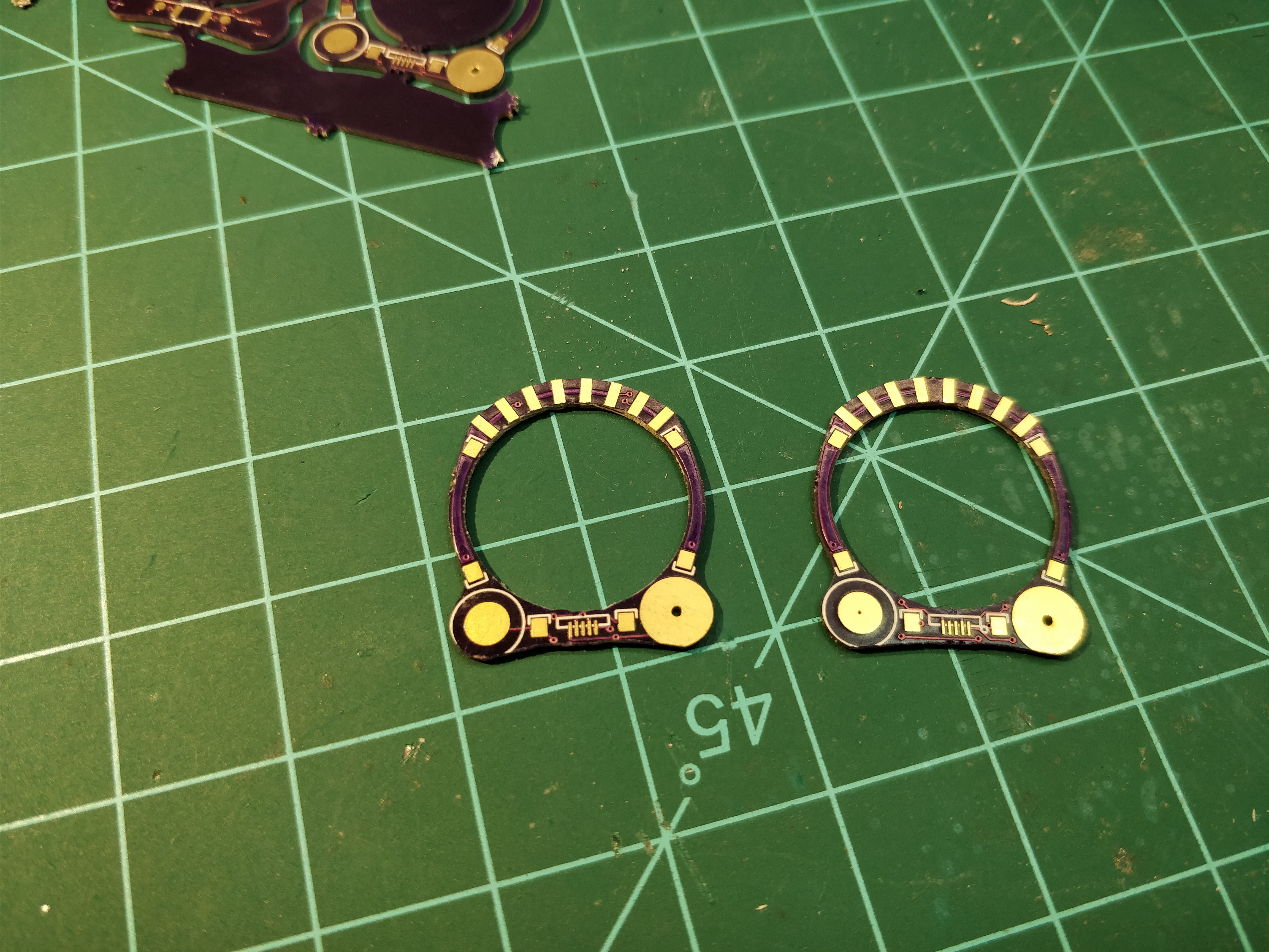
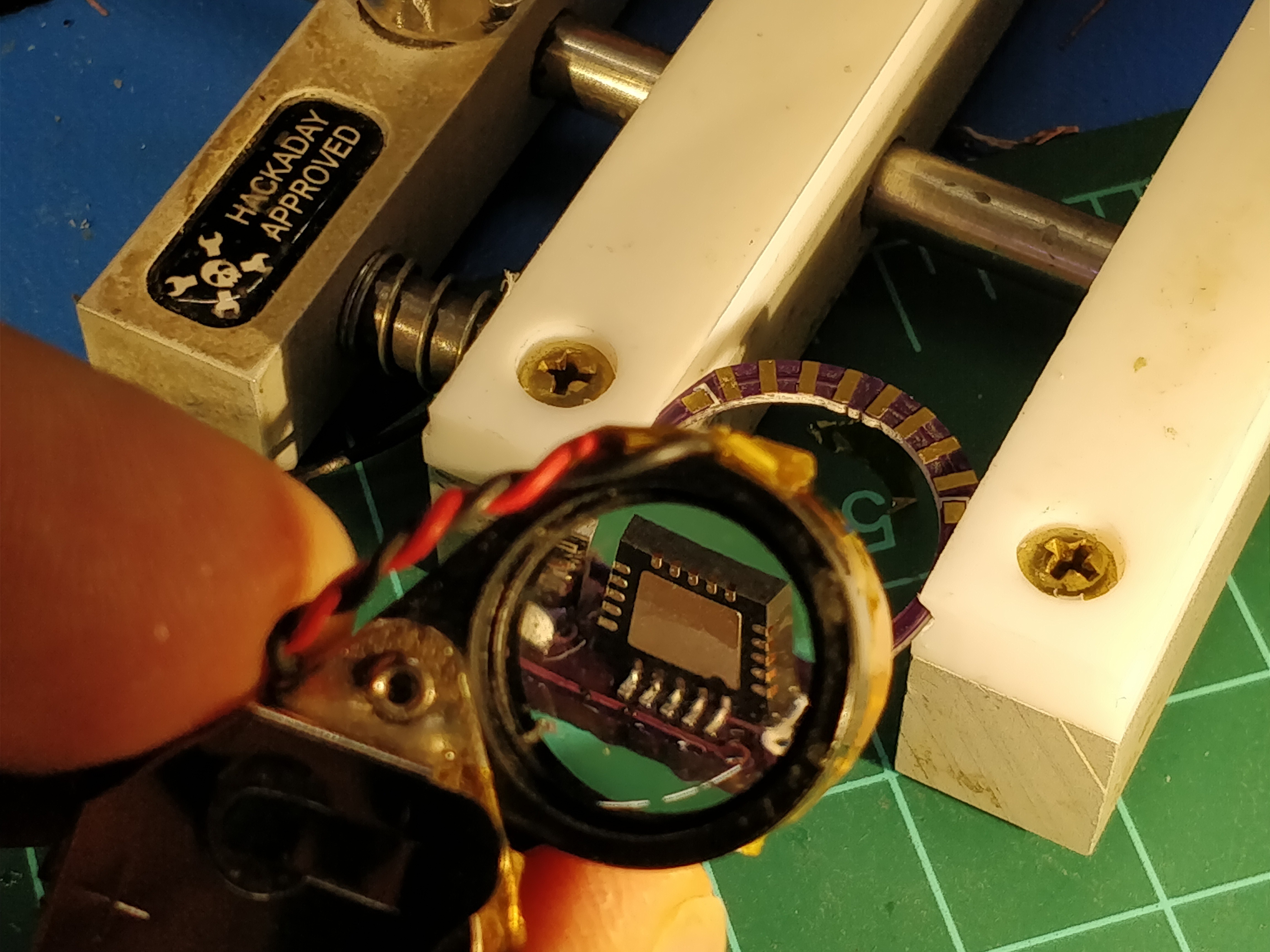
Note the holes on each positive battery contact; these are Zn-air cells, so the vents should be exposed to the atmosphere.
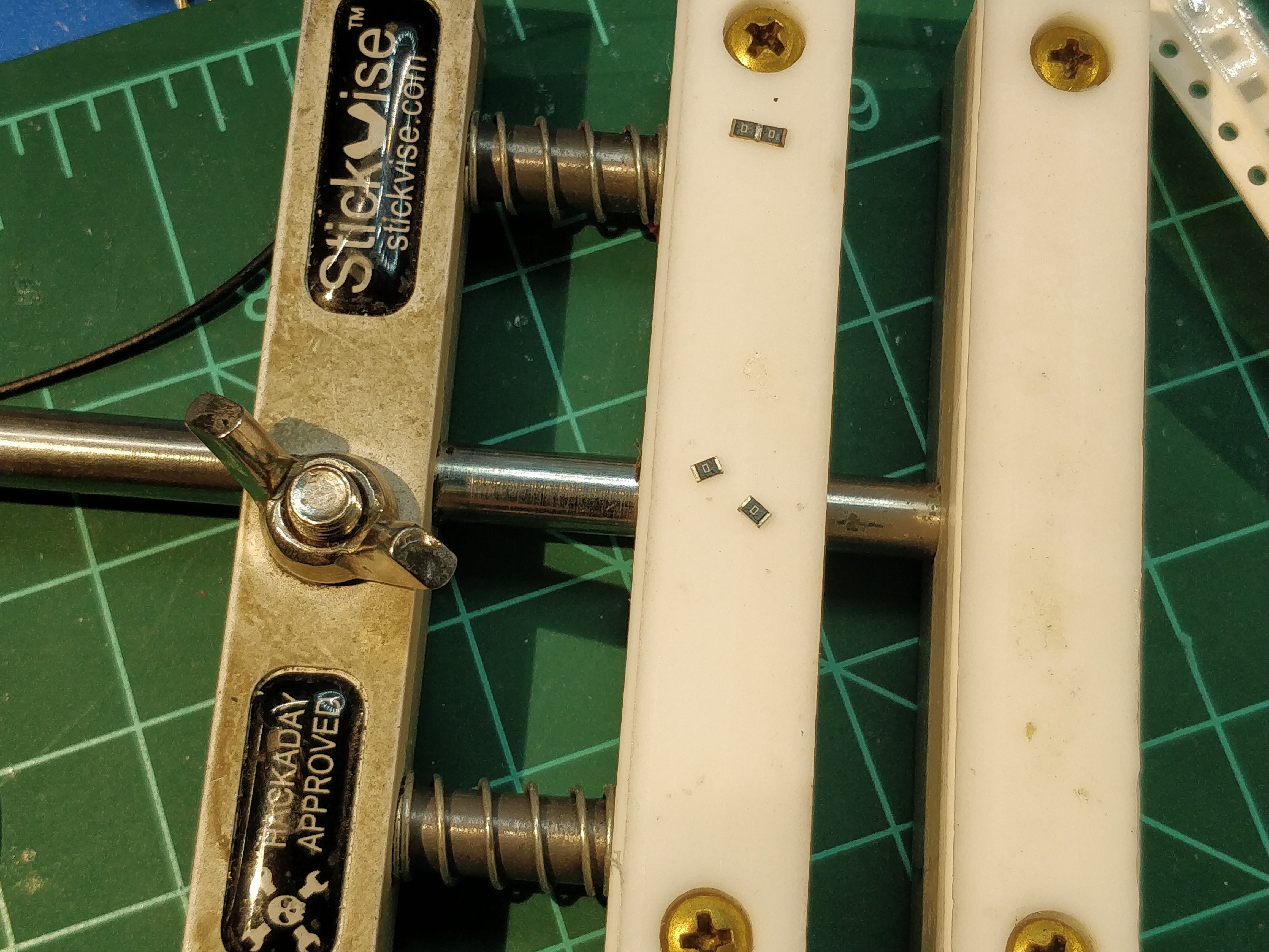
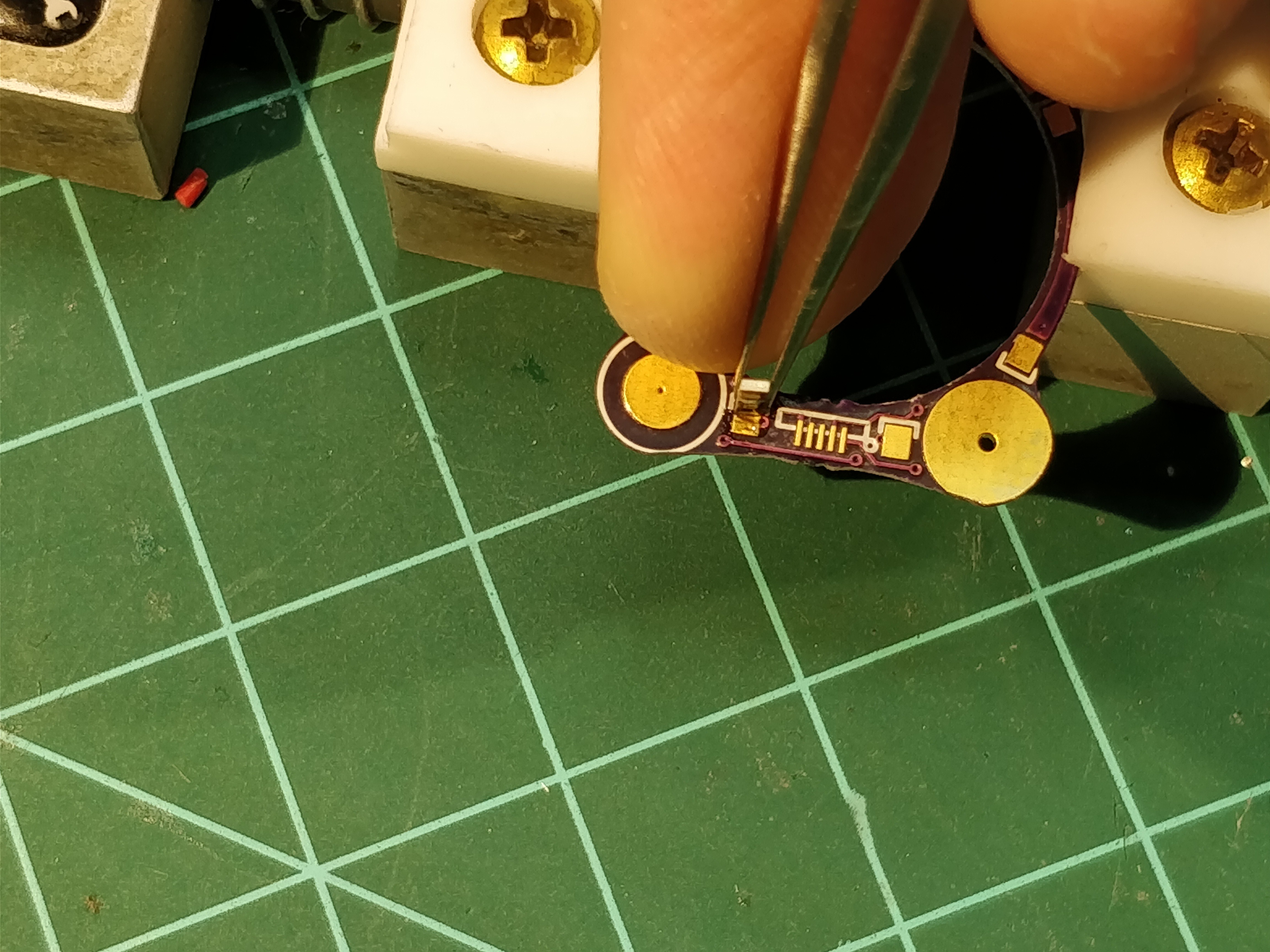
The circuit includes two board-to-board jumpers along with four high-resistance structural resistors, all made from standard 0805 components. I pre-assembled these on a heat-resistant surface (in this case, my PTFE-jawed Stickvise):
Easiest method here is to carefully align the two components with tweezers...

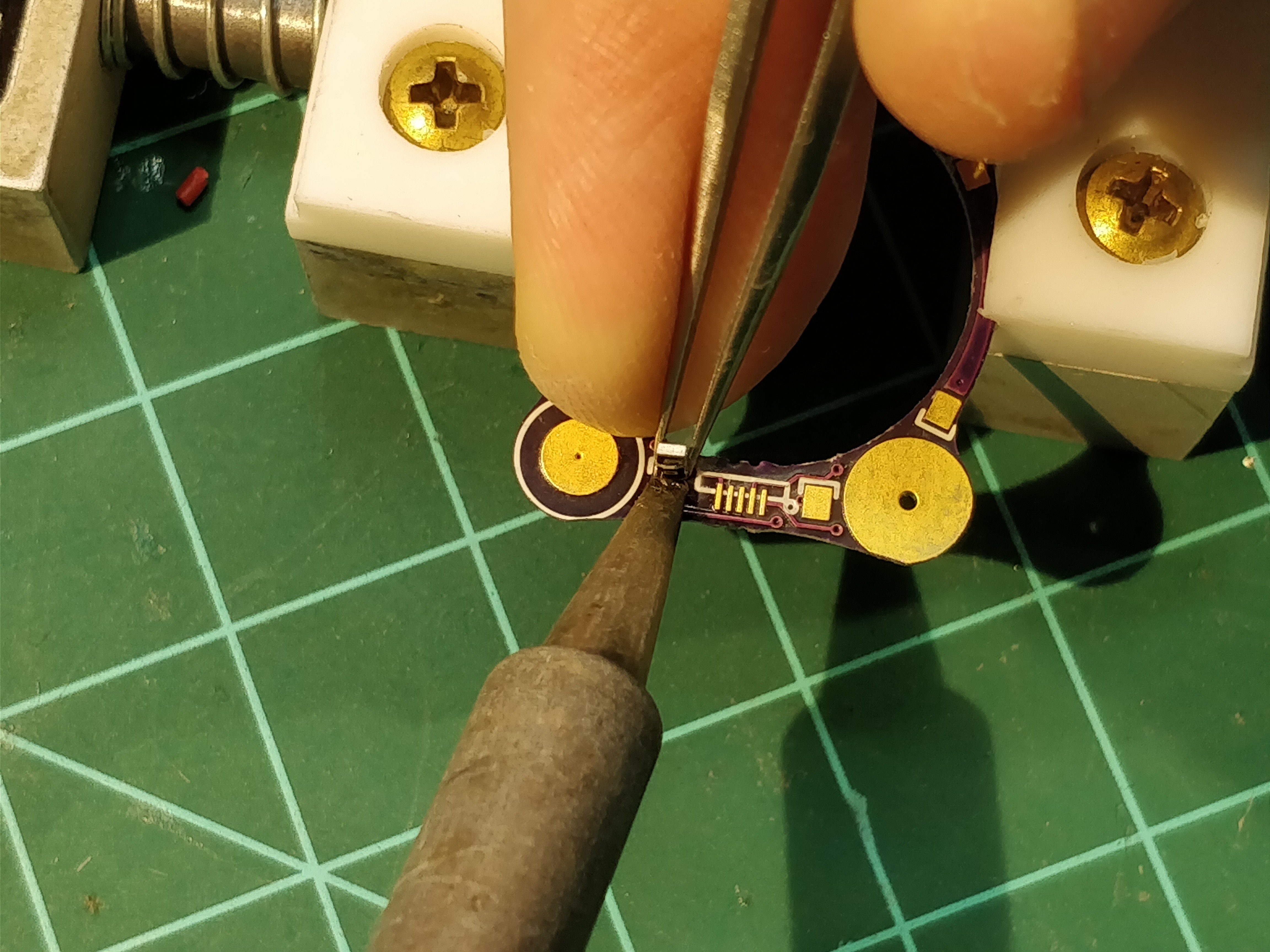
... dab a tiny bit of flux at the junction...
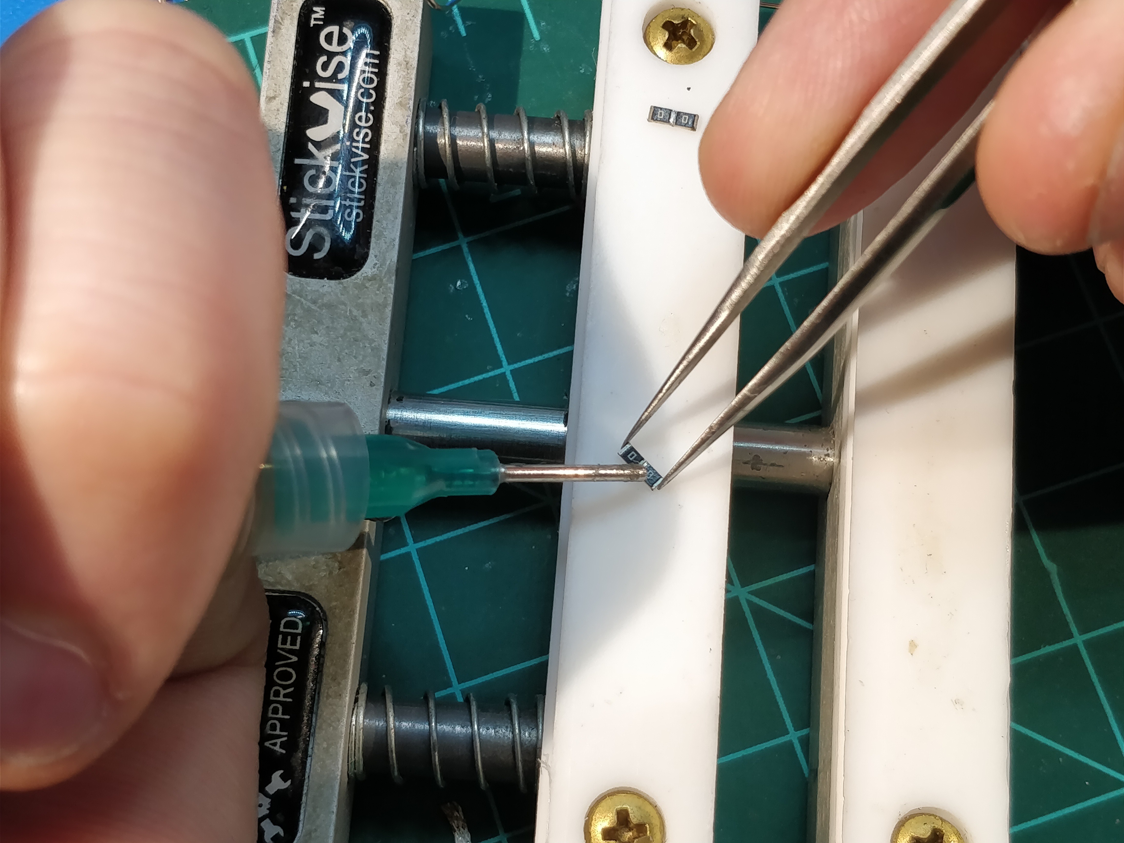
.... and touch the junction with a tinned iron tip.

Done!

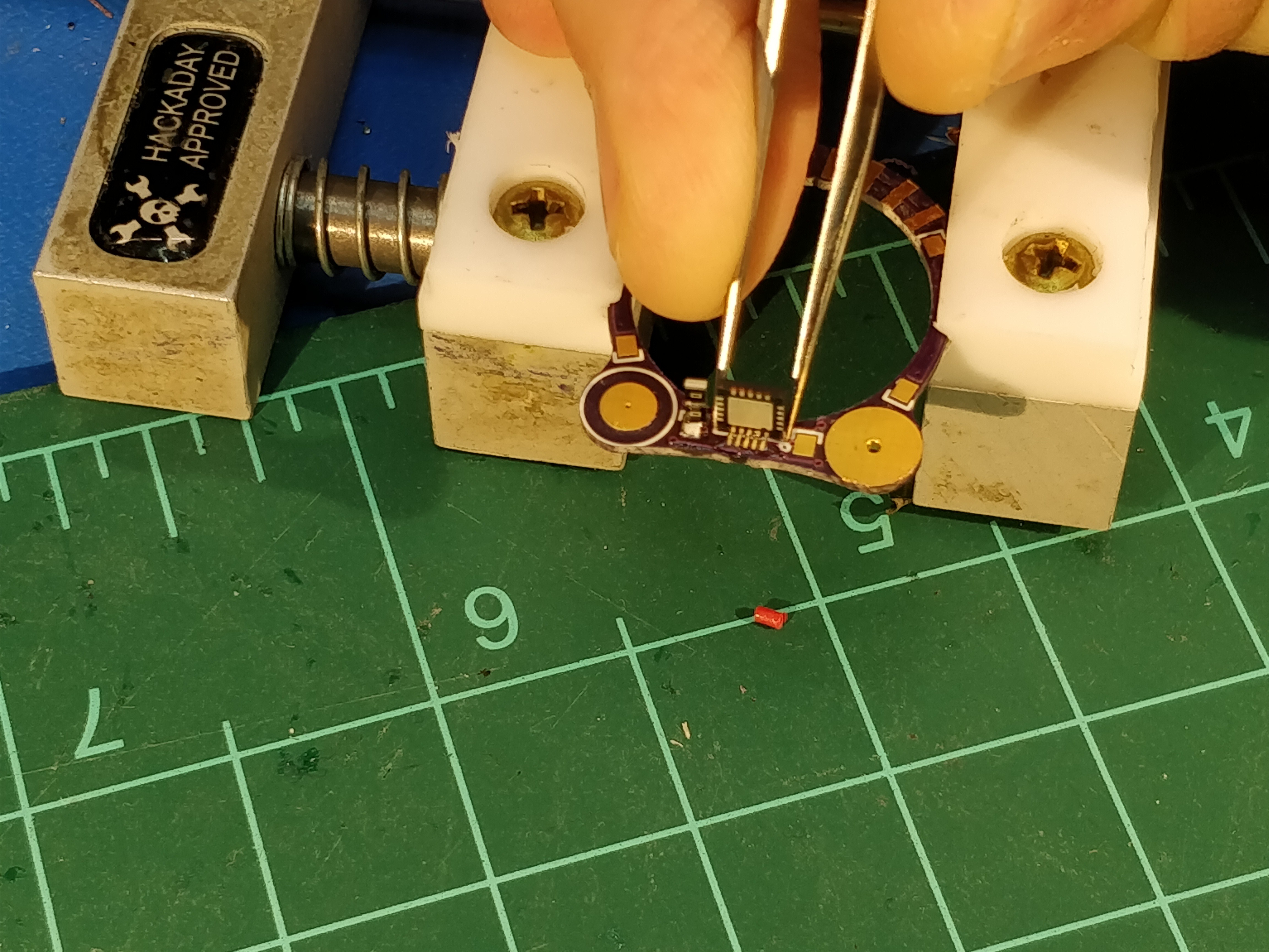
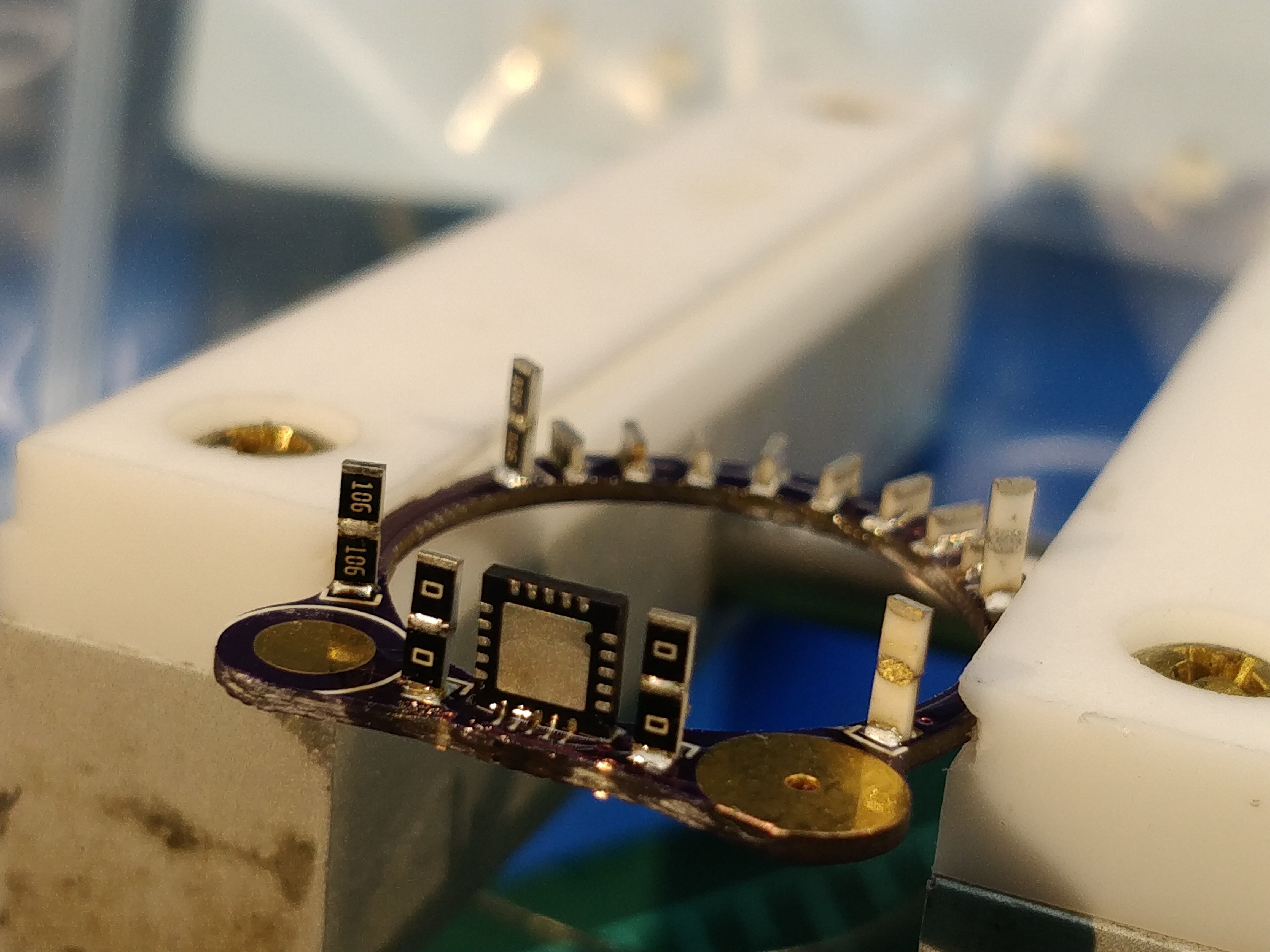
Once I had the 0805 jumpers sorted, I started soldering the vertical components onto the switch side of the ring. I followed my standard SMT soldering procedure here: a drop of flux on the pad...
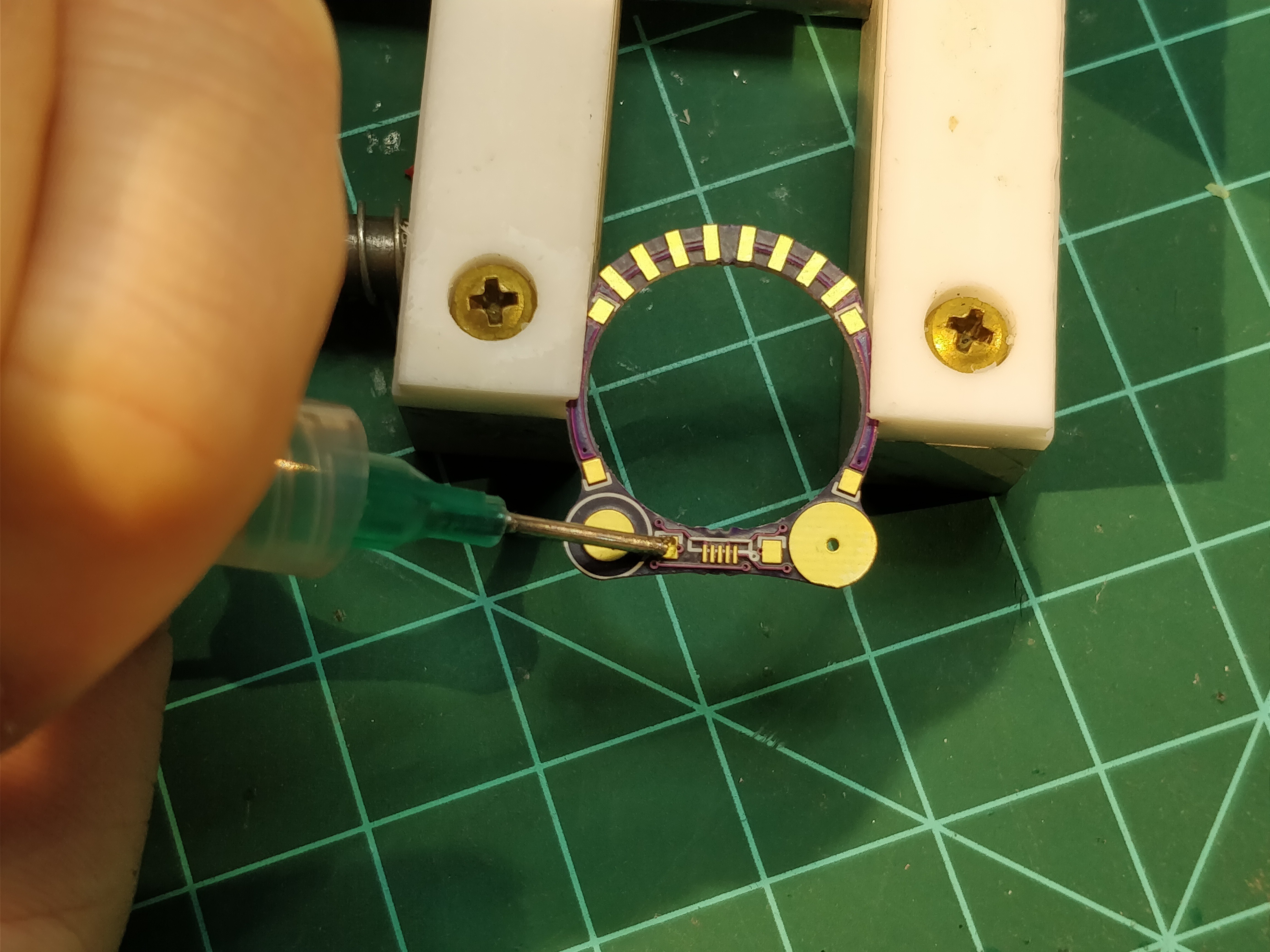
... careful alignment with tweezers...
... and a touch with a tinned iron tip.
The same procedure works for the QFN ATtiny, too, although the iron 'touch' turns into more of a 'scrub'. If this doesn't make sense, I made a QFN hand-soldering video a few months ago that explains the concept a bit better. Note that in both cases, holding the part near the bottom helps a lot to ensure the component is square. Practice makes perfect...

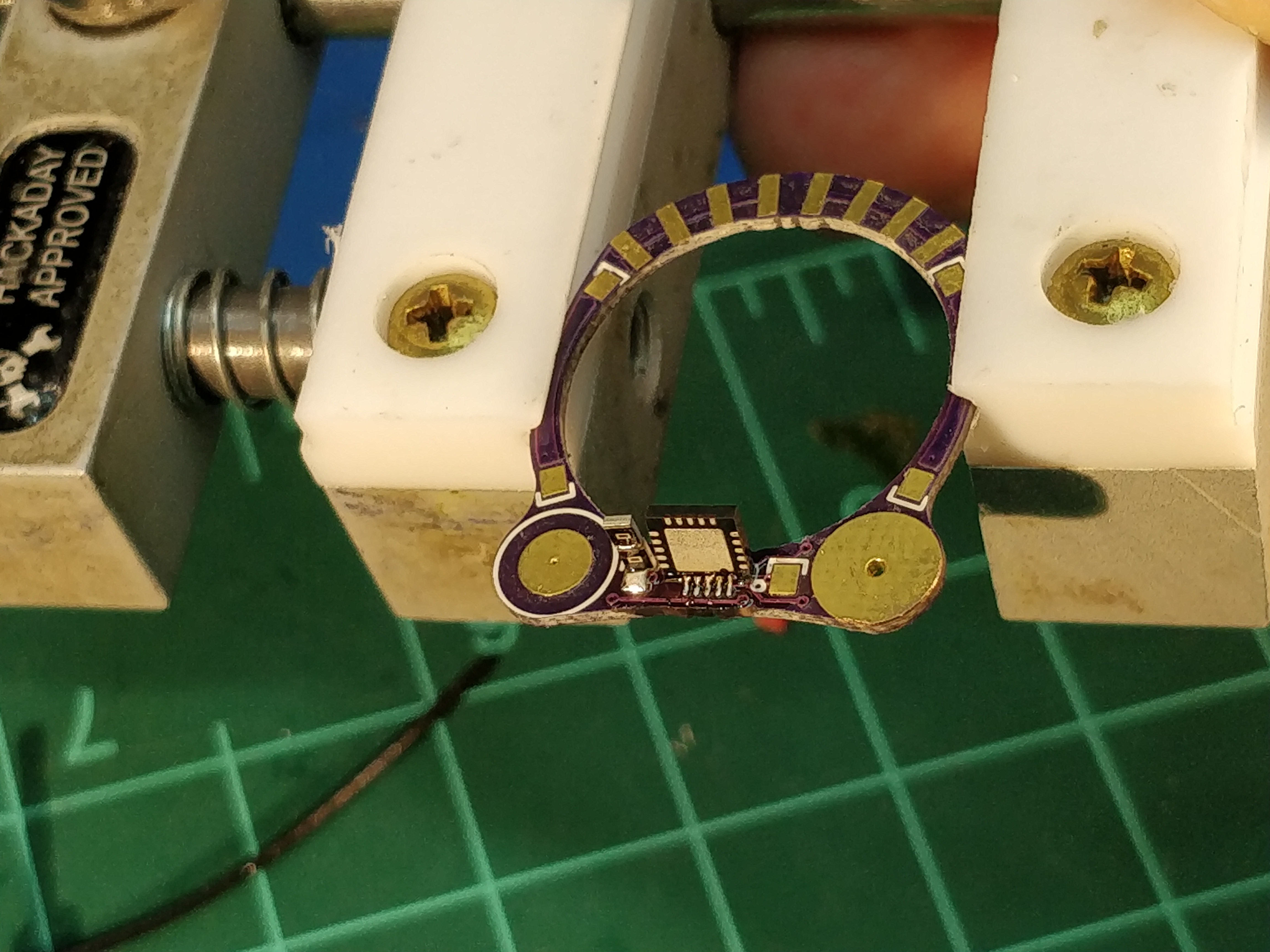
Examination through the loupe ensures we've got a good fillet (not yet defluxed...):
The rest of the parts go on in a similar manner. The LEDs live on either side of an 0508 stubby resistor, so I soldered these onto each side before mating the halves, as shown in this picture from an earlier log:
[keen observers will notice that this is a different copy of the board with the QFN rotated 90 degrees. This was wrong, and I actually had to rework this component after the two halves of the ring were assembled. Yes, solder braid can work miracles.]
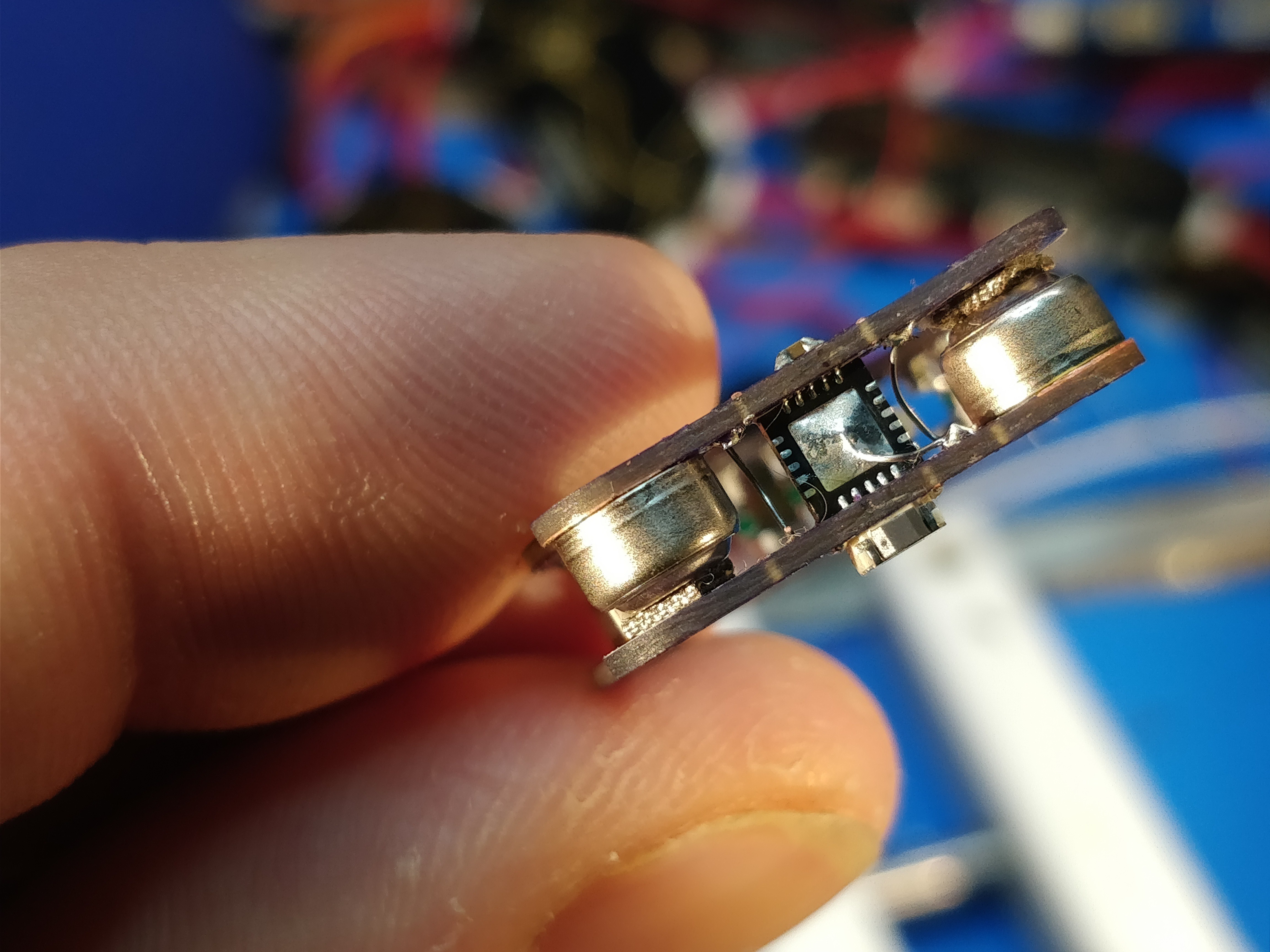
Since the batteries are a bit under 4mm tall -- more like 3.3mm, give or take -- I used a set of tiny spring tabs to fill the gap:
[yes, I didn't really plan the PCB footprint around these tabs, so they hang over a bit. And the QFN definitely needs to be straightened out. Soldering under the camera is a pain.]
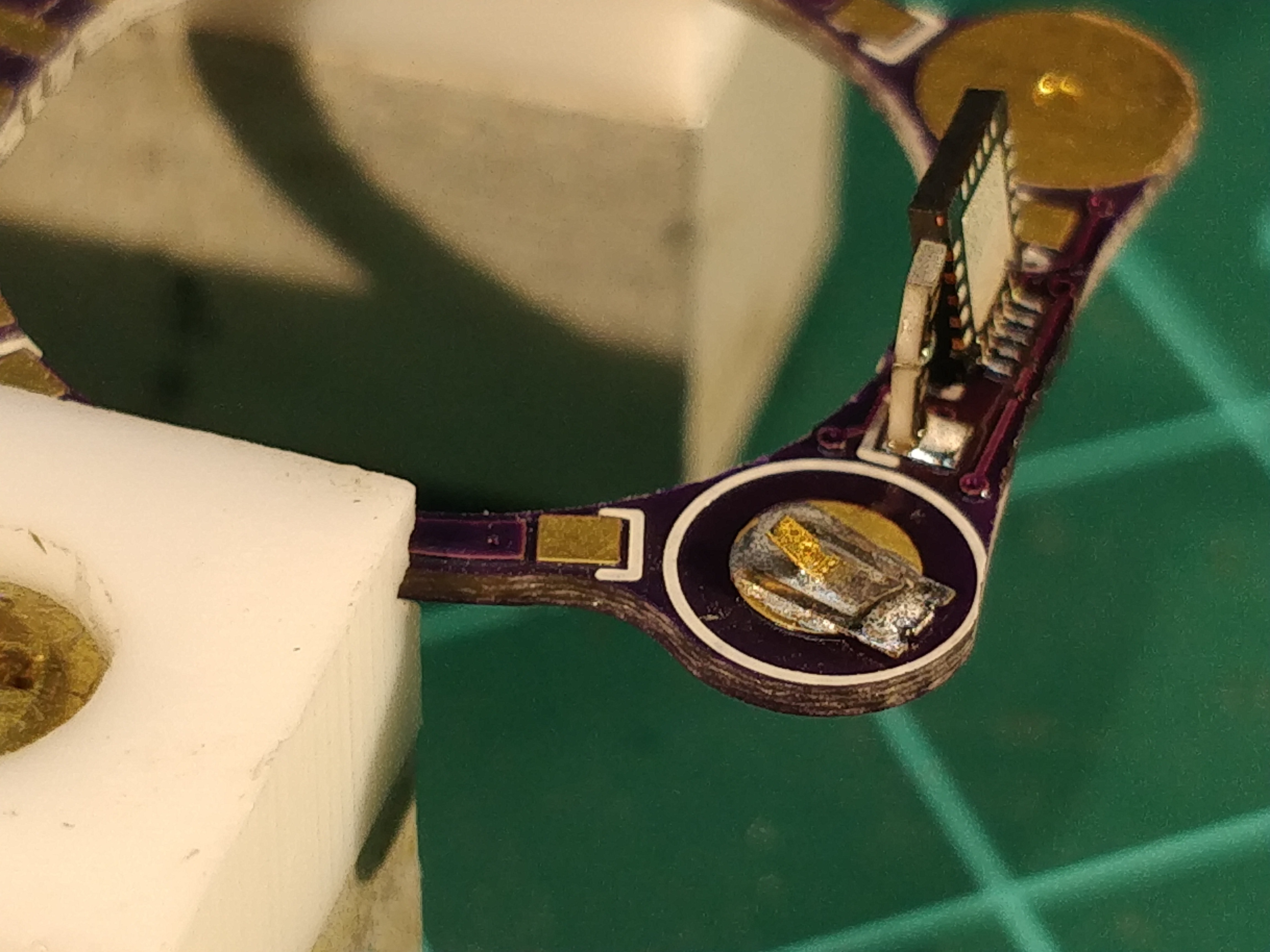
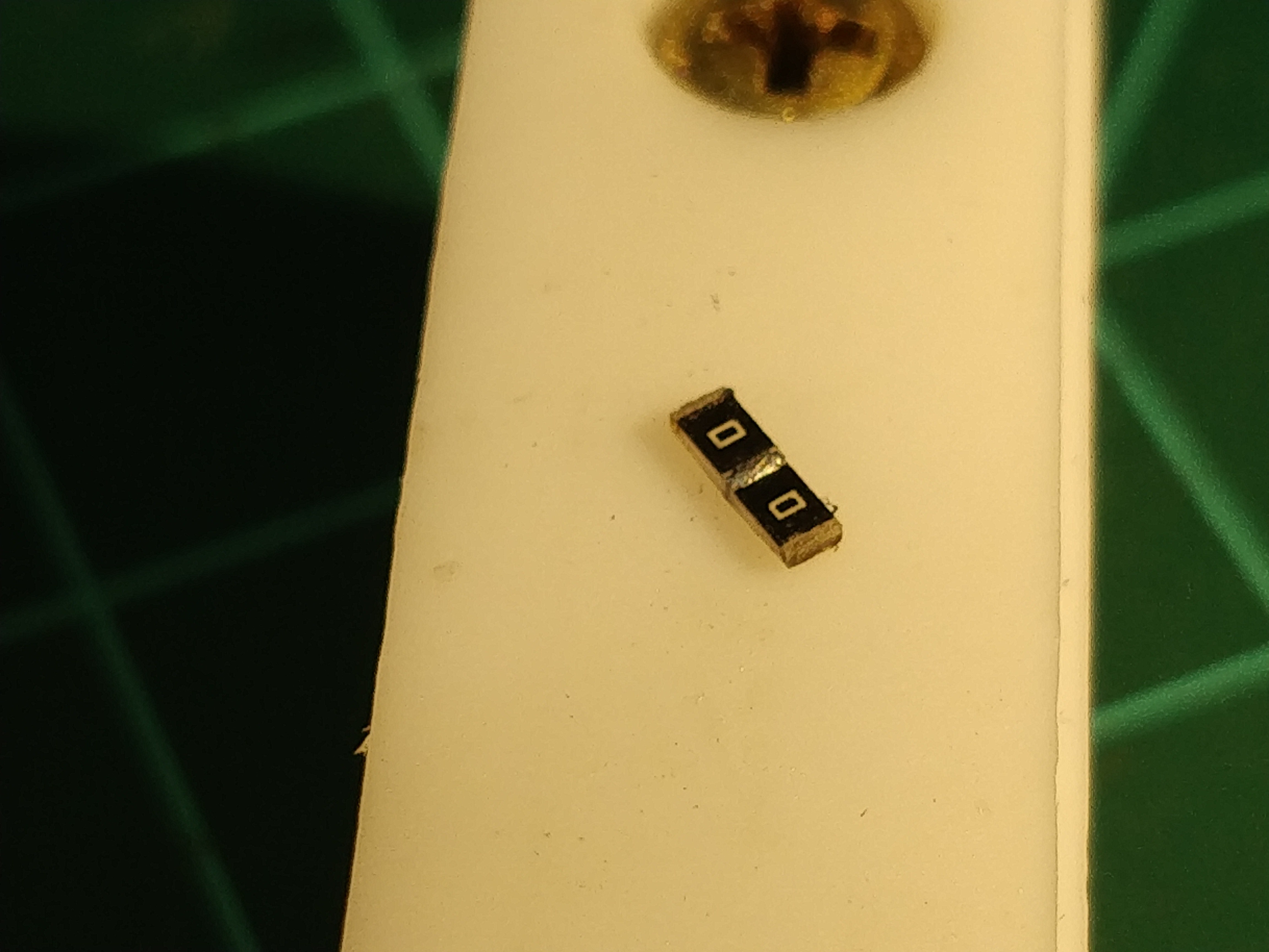
These worked for a time, but eventually the batteries fell out; the tabs plastically deformed after a few insertions and eventually broke. During one of the periodic tab tightenings I attempted over the course of a few days, I pried a bit too hard and the back of the ring actually broke. It seems that I need to treat 0805 resistor stacks like unreinforced concrete columns -- not so great in tension, as the caps tend to pop off:
Fortunately none of the pads were damaged, so I replaced the resistor jumpers with lengths of wire. I used tiny scraps of self-adhesive conductive RF gasket for the batteries, which seems to work but still doesn't seem ideal:
Just popped in a new set of batteries, so I'll wear the repaired ring for a bit and see if any other weaknesses pop up. I'm starting to make a list of improvements for the next rev which I'll share next time, as this log is already long enough.
Discussions
Become a Hackaday.io Member
Create an account to leave a comment. Already have an account? Log In.
Great project, your Stickvise has a great patina, good to see it getting used.
Are you sure? yes | no
Yesterday I soldered 0.4mm pitch 40 pin display connectors and they worked (after a few tries). There was something about the focus of it that I loved - the art of soldering. This post inspires me to want to try and build something similar. The thing that I keep wondering is if it's possible to put in some kind of communication - what the smallest radio one could find and would it fit? :)
Are you sure? yes | no
congrats on the 0.4mm pitch display connector -- I've found moving from 0.5 to 0.4 is quite a leap! Re: radio, I think the key would be to find an integrated SoC of some kind that puts the RF stuff in the same package as the microcontroller. My guess is most of the QFN options would require at least a few bodge wires to pull in pads. The tough bit for me would be getting a toolchain sorted; I'm comfortable with AVRs and STM32s, but I haven't done a (for example) nRF52832 project. Agreed that some kind of communication would be ideal, though. Push notifications on a ring!
edit: https://imgur.com/a/Q9Npx
Seems doable, the top and bottom of the chip don't have a ton of required connections. Would be interesting to get the crystal working. This chip is 6x6mm, so one could also use taller batteries.
Are you sure? yes | no
Amazing soldering skills you have ! Great creativity, very well done. And even better, thanks a lot to have documenting in such details !
Are you sure? yes | no