 Kuro
KuroIt's been a long time since the last update, sorry guys. I've got rather busy, then came end year and I went to visit my family, without any contact with the project.
Anyway, I was able to finish the project just before leaving, but had no time to post about it. In this post I'll talk about the software development and I'll try to finish the project as soon as possible.
There were some problems, mainly with the PCB, as I noticed later. I didn't feel the problems were big enough to make me redo the PCB, so I'll just leave it as it is right now.
The first problem was related to the LCD data bus. I didn't know that A6 and A7 pins on Arduino Nano were input only, and these two pins were used as D6 and D7 data lines to the LCD. This was fixed rather easily by using other available pins on the side of the board. I didn't even swap that vertical pin header to a right angle one after discovering that.
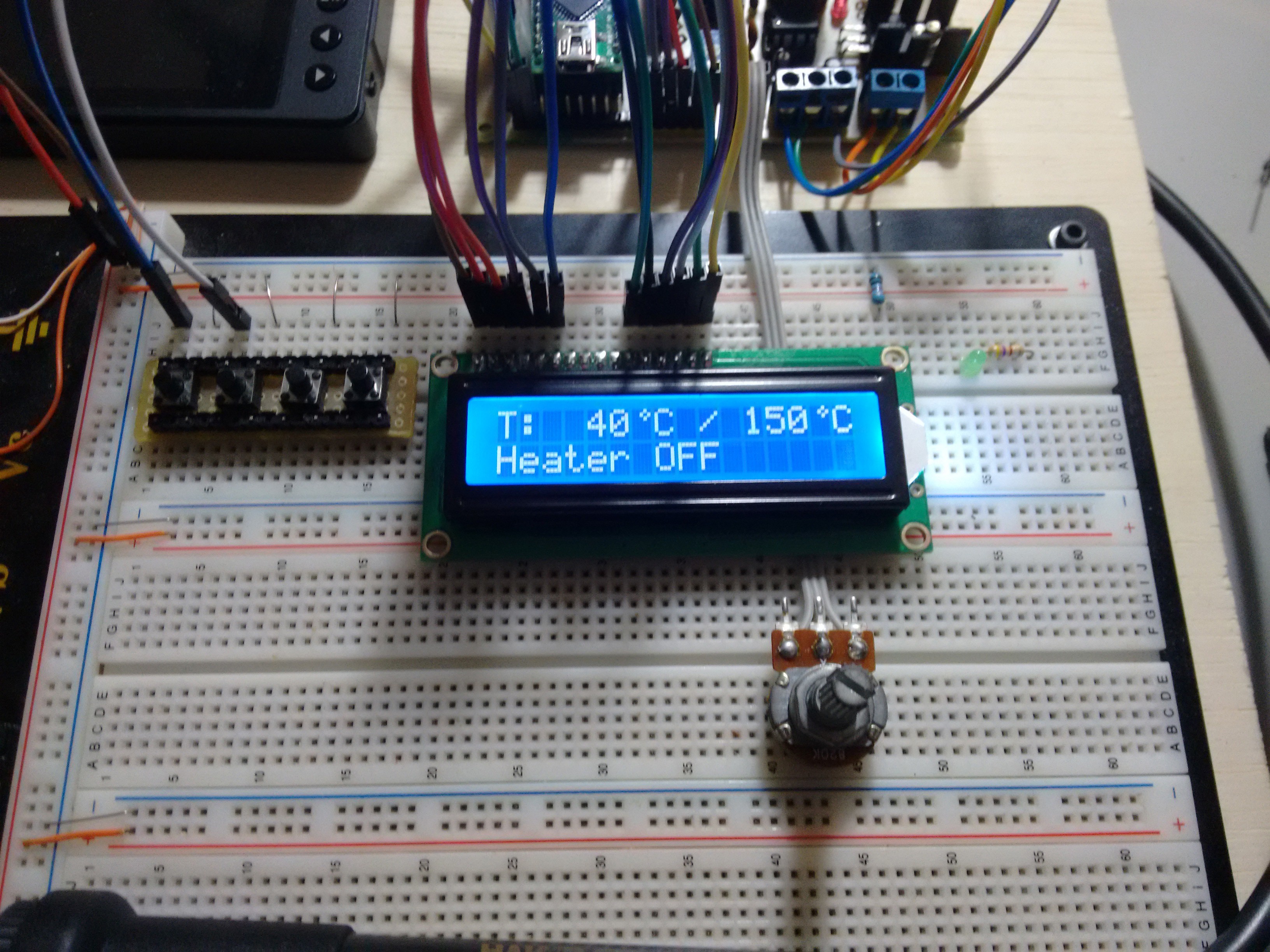
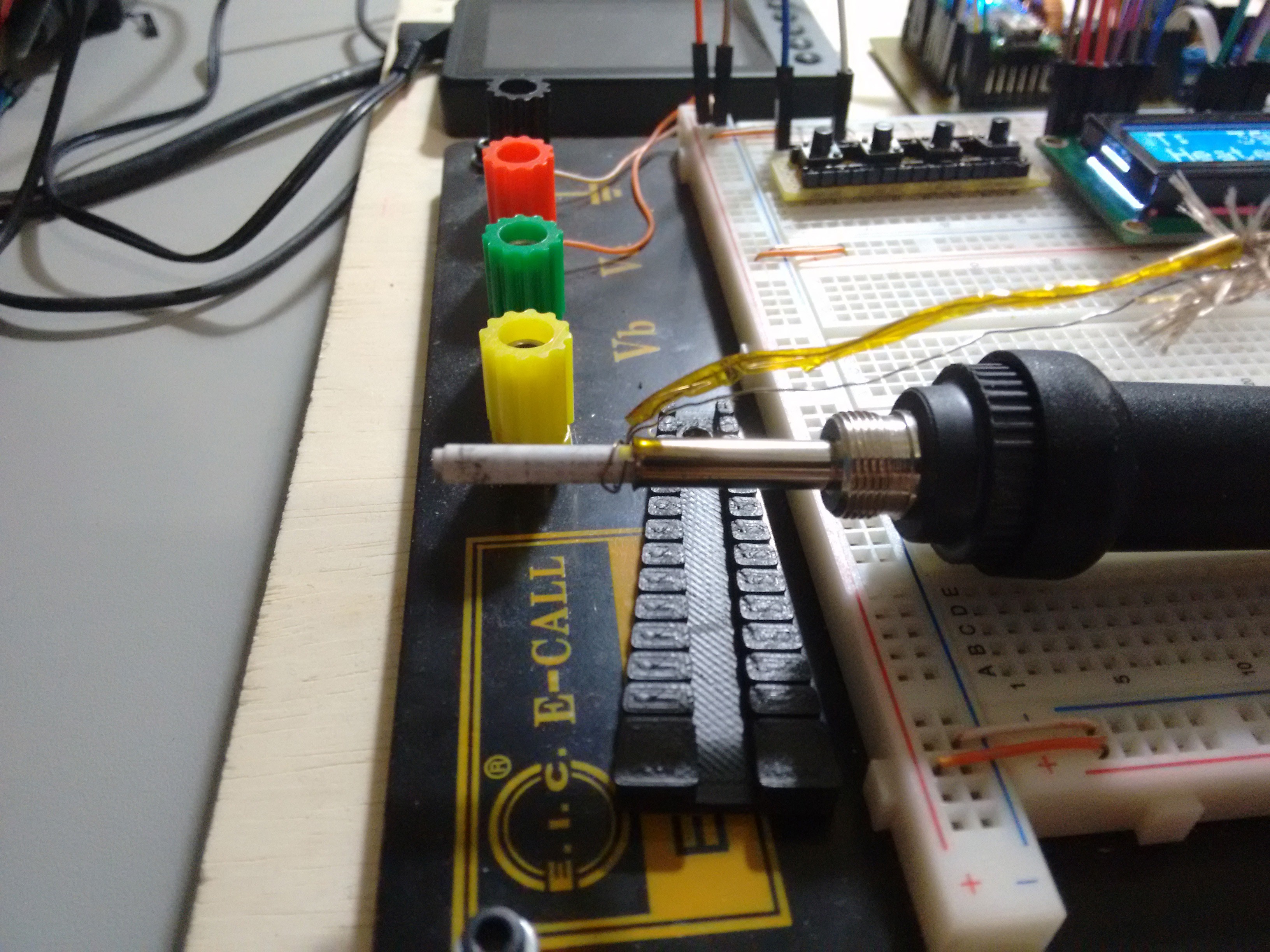
Now, I had to do the software. I prepared a breadboard with the LCD, some tactile switches and a potentiometer. I also connected the soldering iron and attached a thermocouple to the heating element.

As I had noticed before that the PTC resistance was almost linear over a wide temperature range, I chose to use a linear function to calculate the temperature. I measured two different temperatures and the corresponding analog value to calculate the equation.
In the code you can uncomment the following lines to show the analog value read by the Arduino:
lcd.setCursor(13, 1);
uint16_t temp_analog = 0;
temp_analog += analogRead(TEMP_PIN);
temp_analog += analogRead(TEMP_PIN);
temp_analog += analogRead(TEMP_PIN);
lcd.print(temp_analog/3);
I got the analog values with the iron at 30C and 450C, as measured in the thermocouple. These values were 228 and 590 respectively.
The equation will look like:
where Y is the temperature and X is the analog value read from the sensor. You will need the two analog values and the two temperatures to calculate "a" and "b".
To find "a", subtract your higher value temperature from your lower value temperature and divide by the subtraction of their correspondent analog values. Using the values I got: (30C, 228) and (450C, 590) where 30C is 30 degree Celsius and 228 is the analog value.
Now, to find "b" use the the linear equation with "Y" as one of the values you found and X is it's analog value. The value of "a" is the one found just before. Using (30C, 228):
The values of "a" and "b" should then be set in the firmware:
#define EQUATION_A    1.16
#define EQUATION_B    -234.48
Next in the code, I used PID to control the heating element and the code has a PID autotune that should be ran when turning the soldering station for the first time.
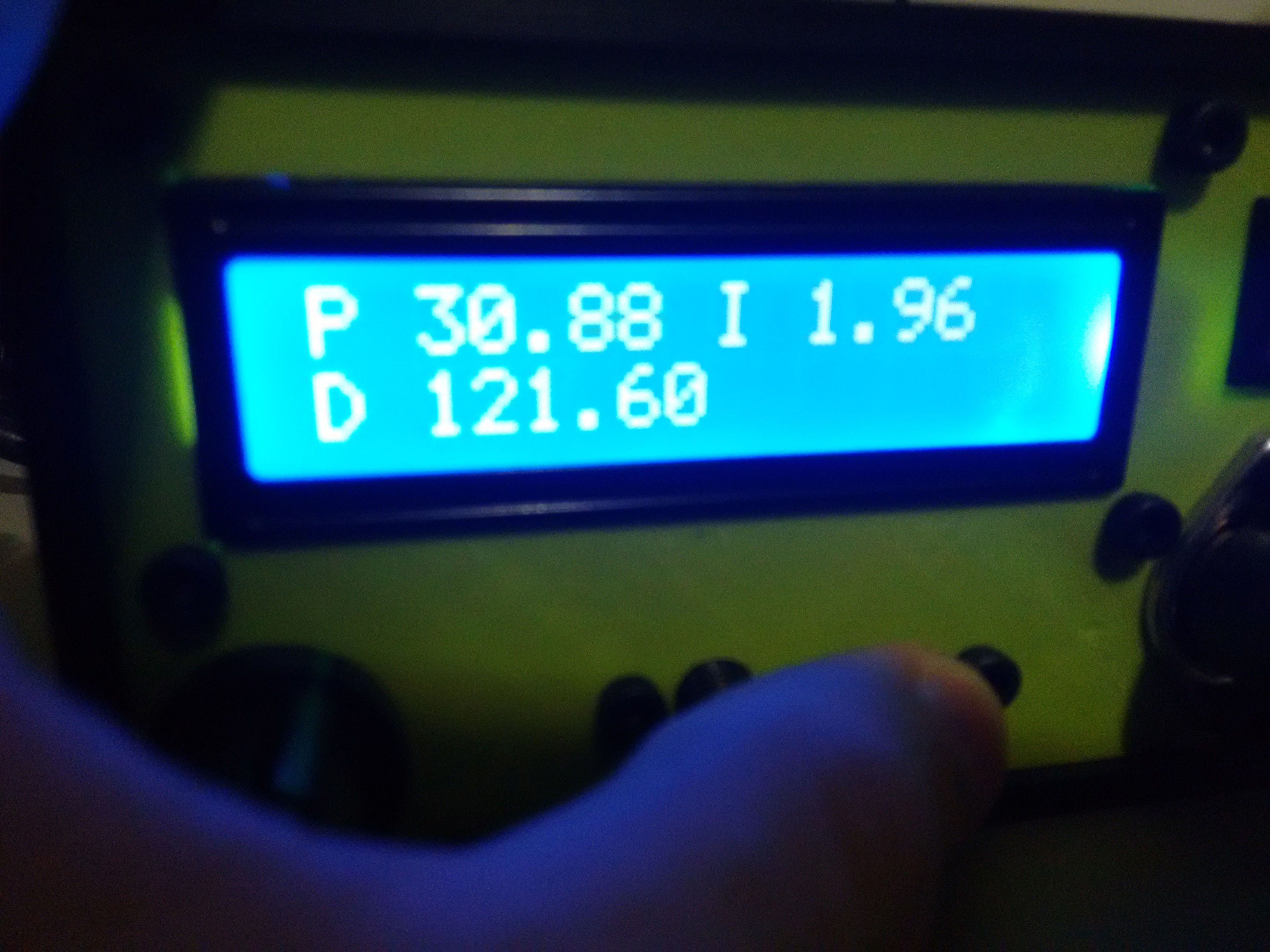
To run the autotune, hold the autotune button and turn on the soldering station. The autotune will then save the values to the EEPROM and these will be loaded every time you use the soldering station. The values can be checked by pressing the autotune button while the soldering station is on.
The only thing I think is still lacking is an auto turn off function.
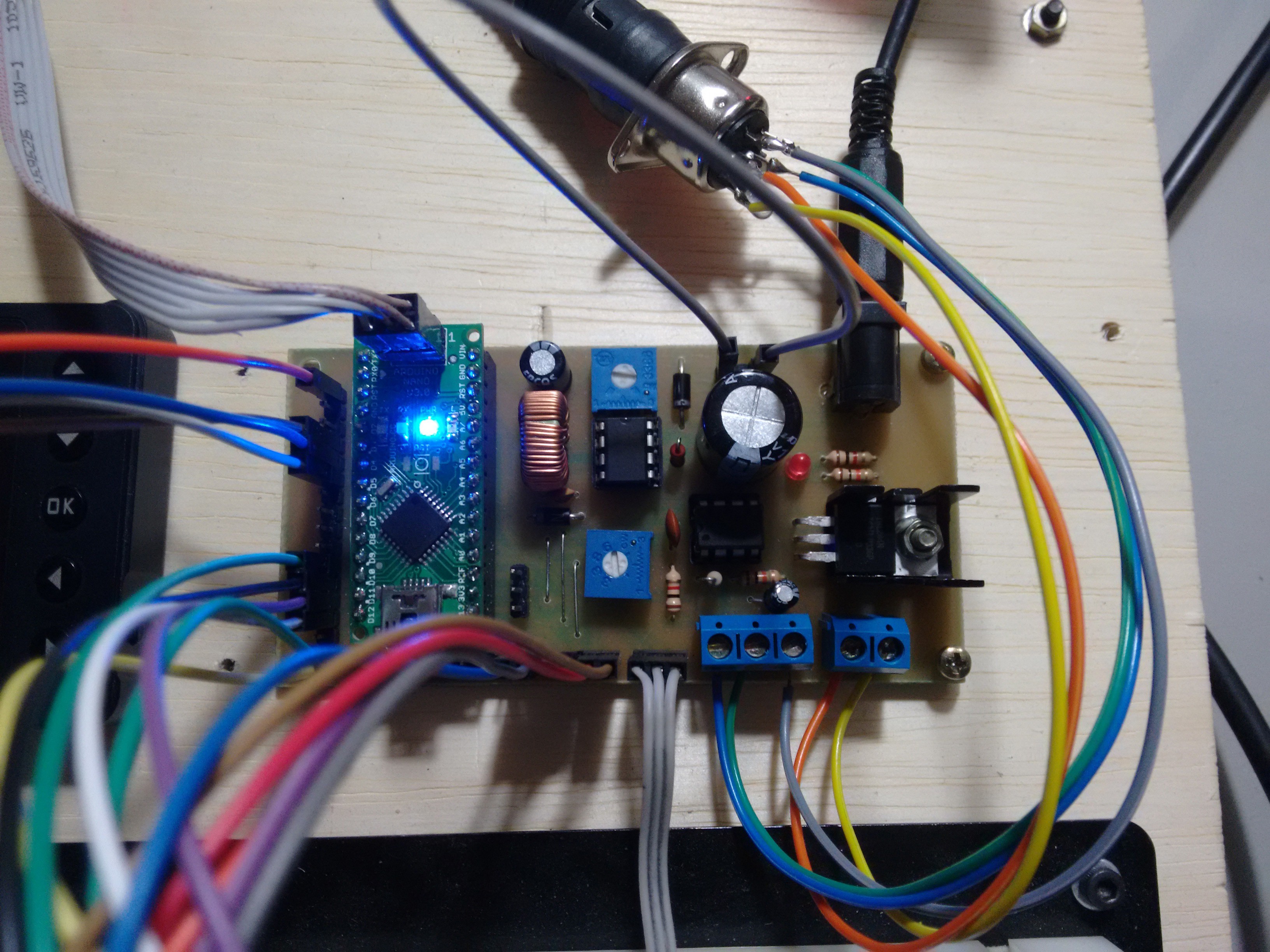
To finish this post, have some more pictures of the development setup:
The code is available here.
Discussions
Become a Hackaday.io Member
Create an account to leave a comment. Already have an account? Log In.