I started this project expecting to use a linear current regulator and a heat sink on the led.
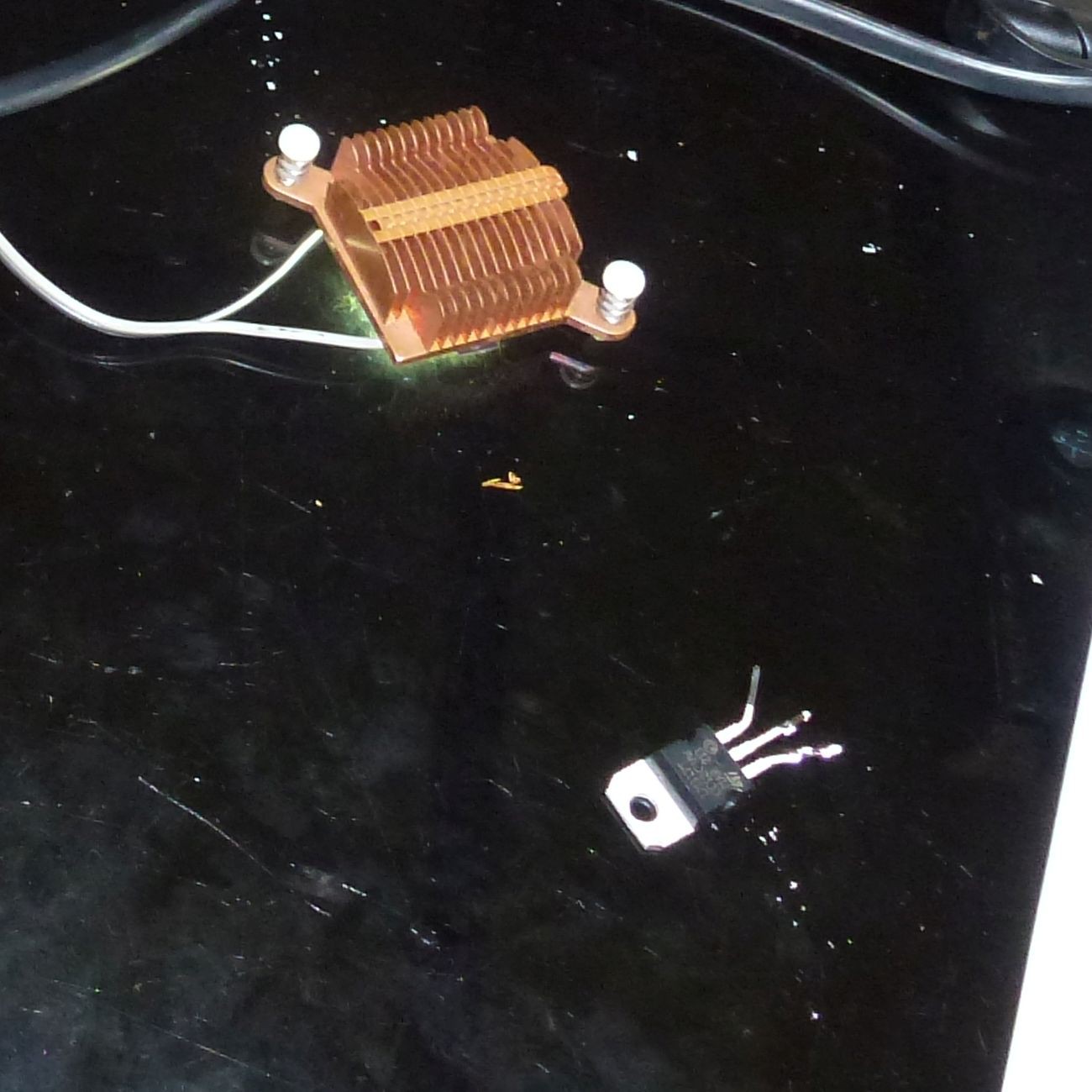
As it turned out the rectified and filtered output from the transformer was so close to correct that introducing a voltage drop from a series current regulator left that LED running below it's rated output.
So I tested it with a simple series resistance of 1.56 Ohms, comprised of 3 4.7 Ohm resistors in parallel.
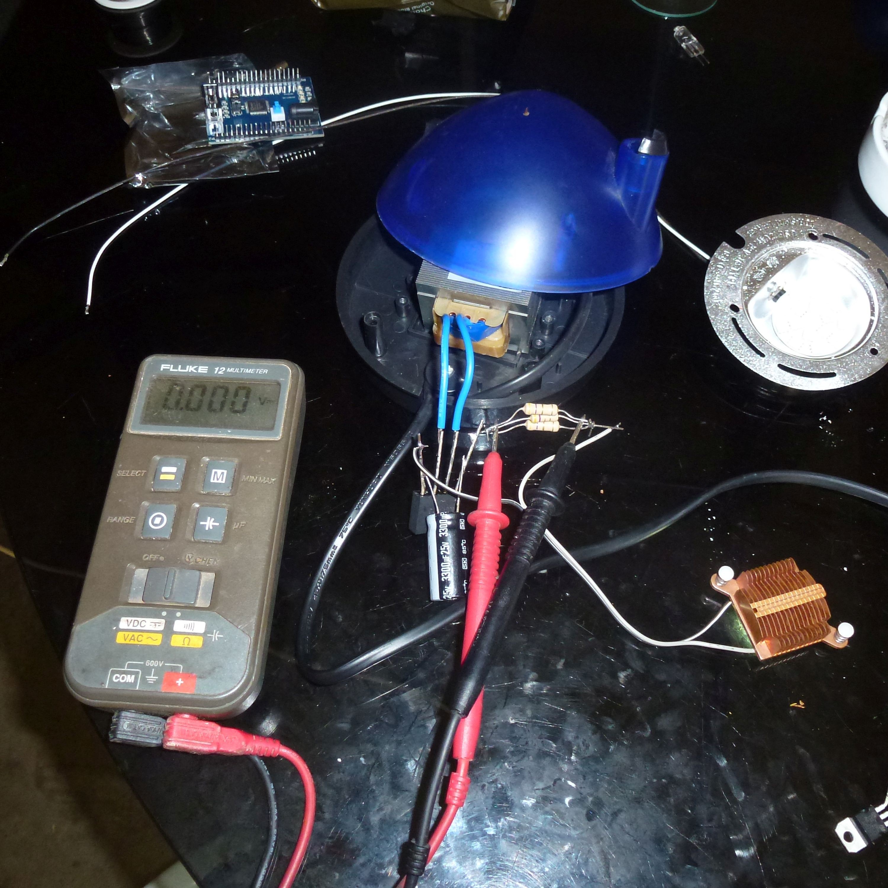
As it turned out this was slightly below the maximum rated power output of the LED.
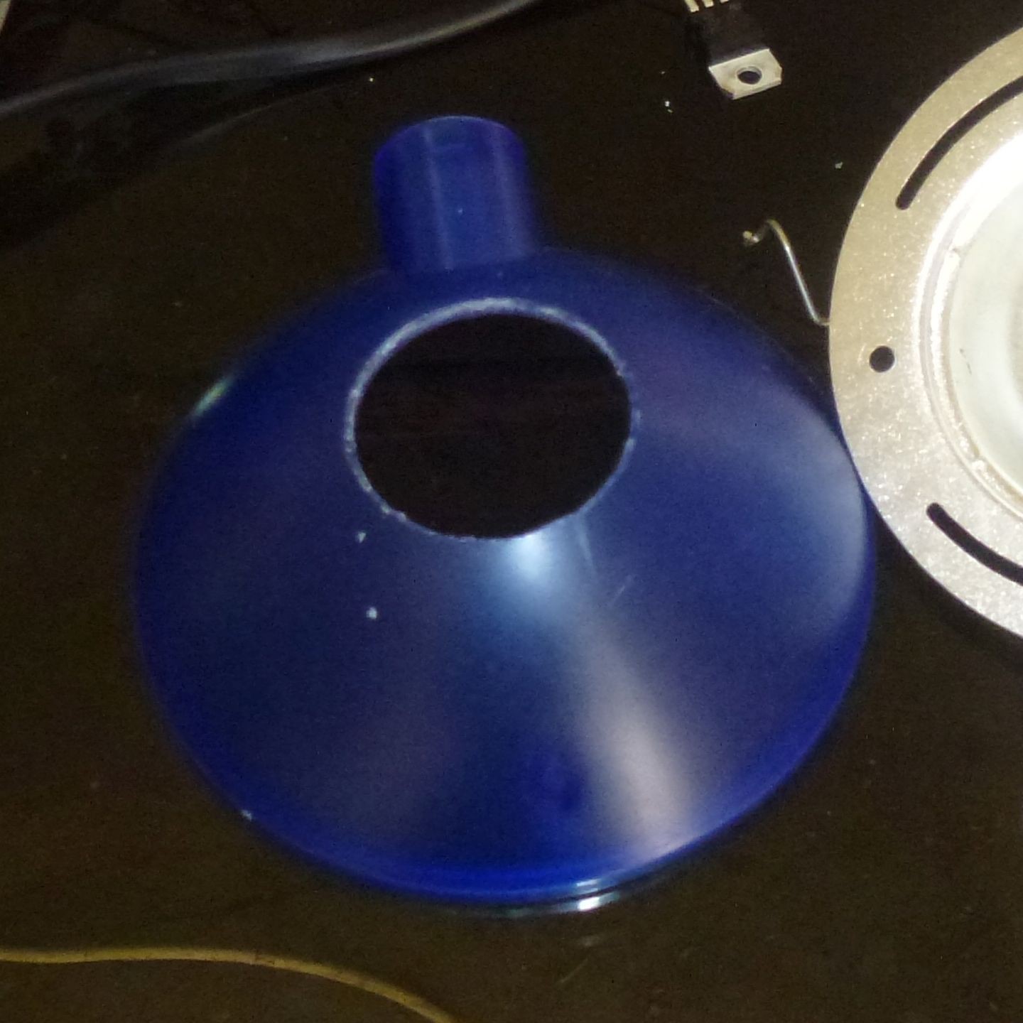
The LED was getting quite hot so i cut a hole in the cover.
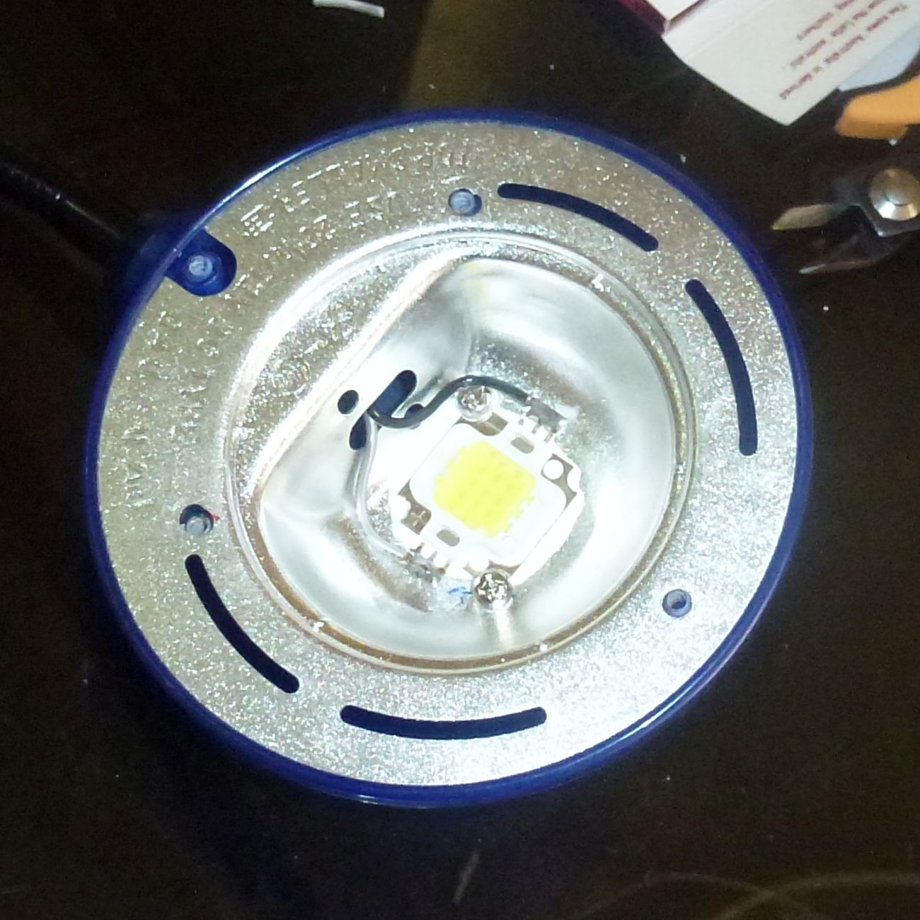
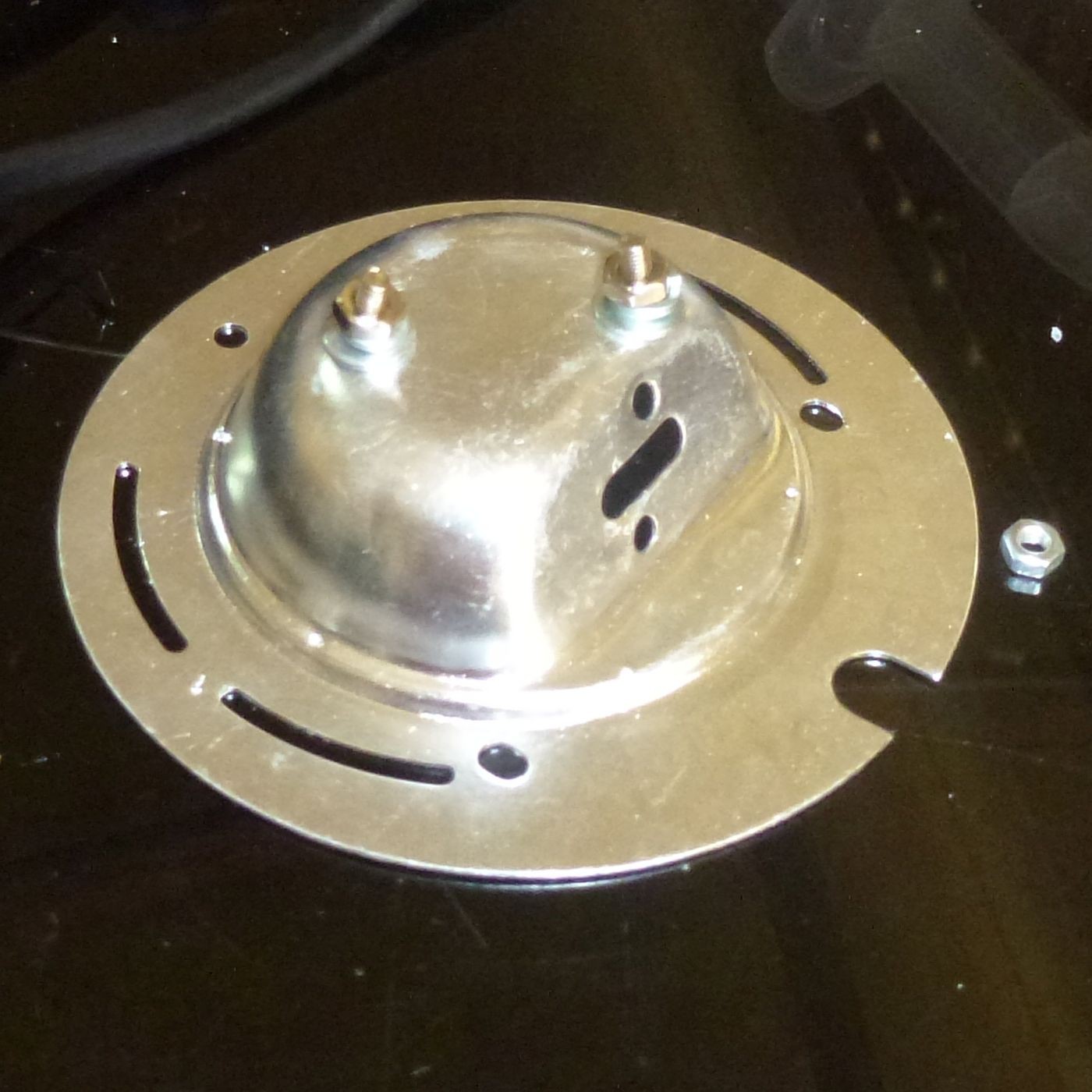
This is how the LED was mounted in the metal reflector. I used thermal paste so that the reflector acted as a heat sink.
I used some heat shrink to keep the connections insulated and used an internal screw post to make sure that the low voltage components can't reach any high voltage connections.
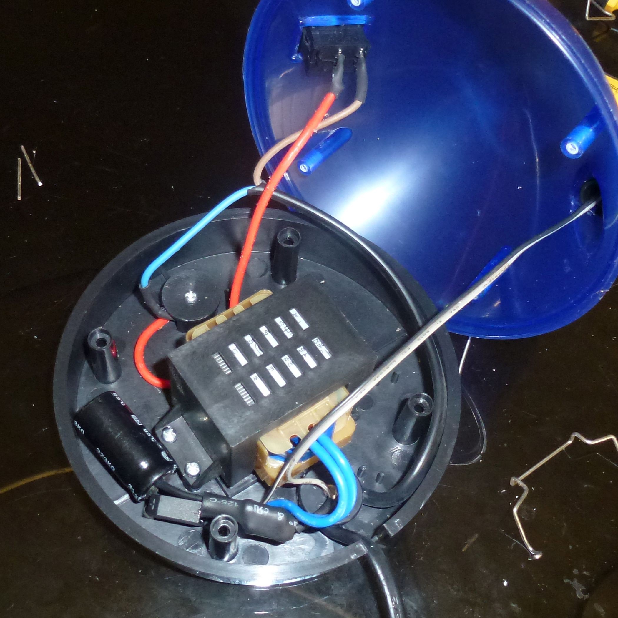
As it turned out the metal reflector does get quite hot and does need a heat sink and small fan. I didn't bother with any extra effort as I only use it briefly at a time in the workroom. So if you make this mod then you have to assess the thermal (fire) and electrical safety aspects yourself.
Also, mains voltage can (and does) kill so don't attempt this if you are not totally competent with mains voltage safety.
This mod was done with a 240 Volt appliance as that is the mains voltage here.
 Hacker404
Discussions
Become a Hackaday.io Member
Create an account to leave a comment. Already have an account? Log In.