 Sebastian Lenartowicz
I decided to start off the build in earnest by building the X-axis, because I felt like that was one of the components that needed the most work. The basis for the X-axis is the print head carriage off of a B+W inkjet fax machine, with a total travel distance of about 9 inches. Because of its previous function, it needed some major modification before being ready to be put to use in a 3D printer.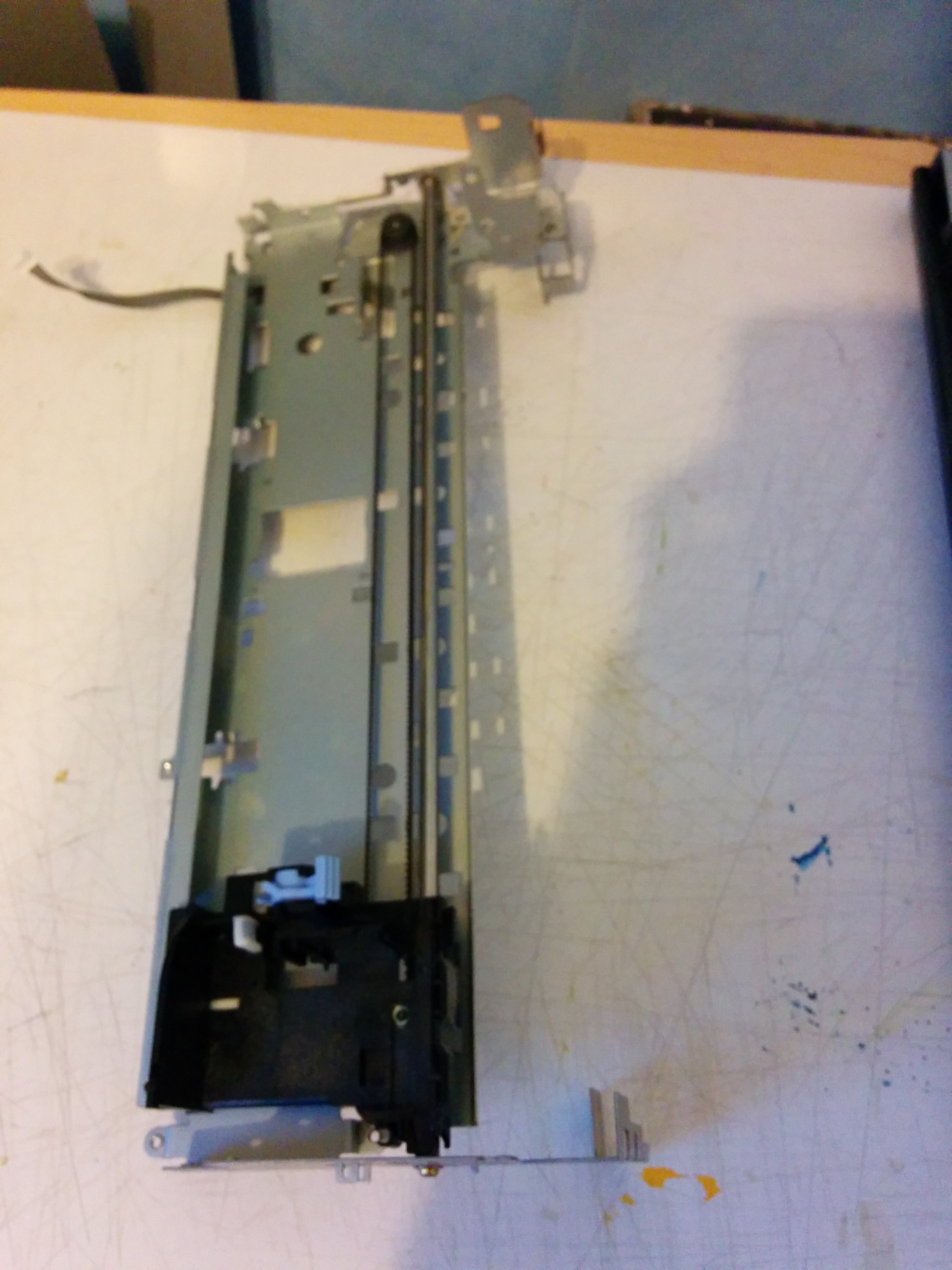 The first, and biggest, problem is the wobble in the print head itself - the way it's designed, it uses only a single rail and the force of gravity to keep it stable and on target relative to the paper. This is unacceptably error-prone when it's being used for a 3D printer (as it will be moving around in more than one axis, and might jerk around and move off-target as it's being adjusted in the Z-axis).
To remedy this, I decided to add a second rail and a slider for it, to keep everything stable without relying on gravity.
Before starting to work on the rail, I removed several protruding bits of metal that might catch on things or cause problems when the printer is finally in operation.
To mount the rail, I started by drilling out one of the pre-existing holes in the carriage frame (which had a matching hole on the far end along a straight path) to make it a little wider (it was 5mm before, and 6mm after). This was to accomodate a smooth rod that I extracted from a broken HP office laser printer (of uncertain model number) of roughly the right length.

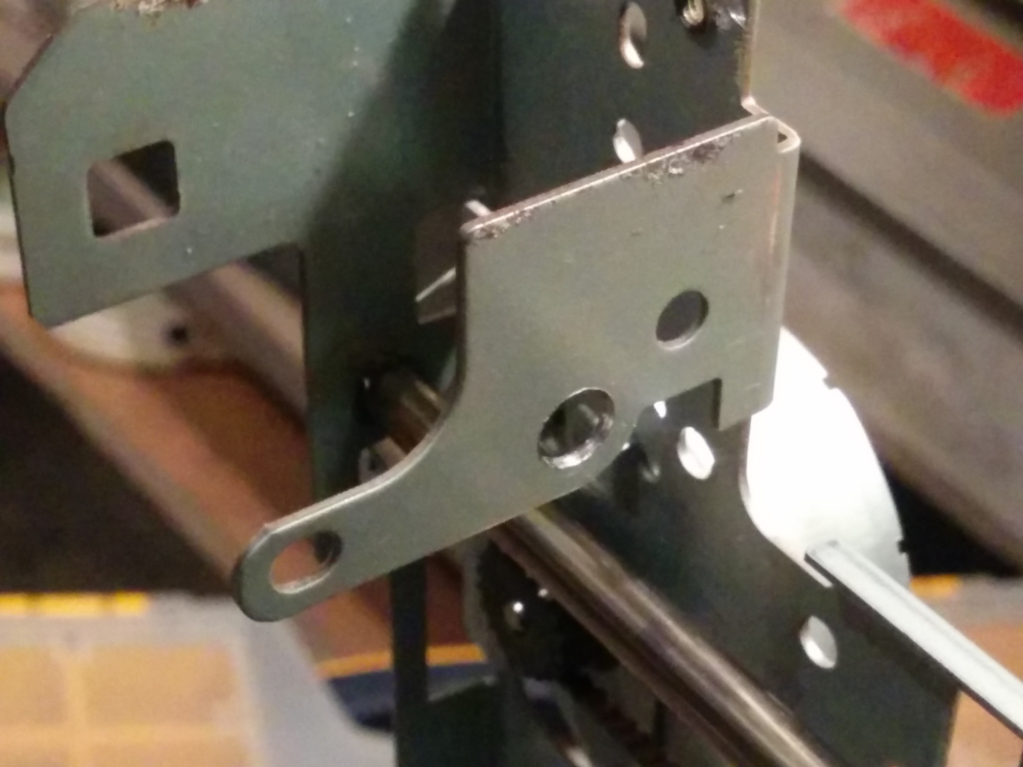
The two images show the hole before and after. I also ground off that little bit of metal next to it and sanded it down, so the slider will be easier to make and have a longer travel length.
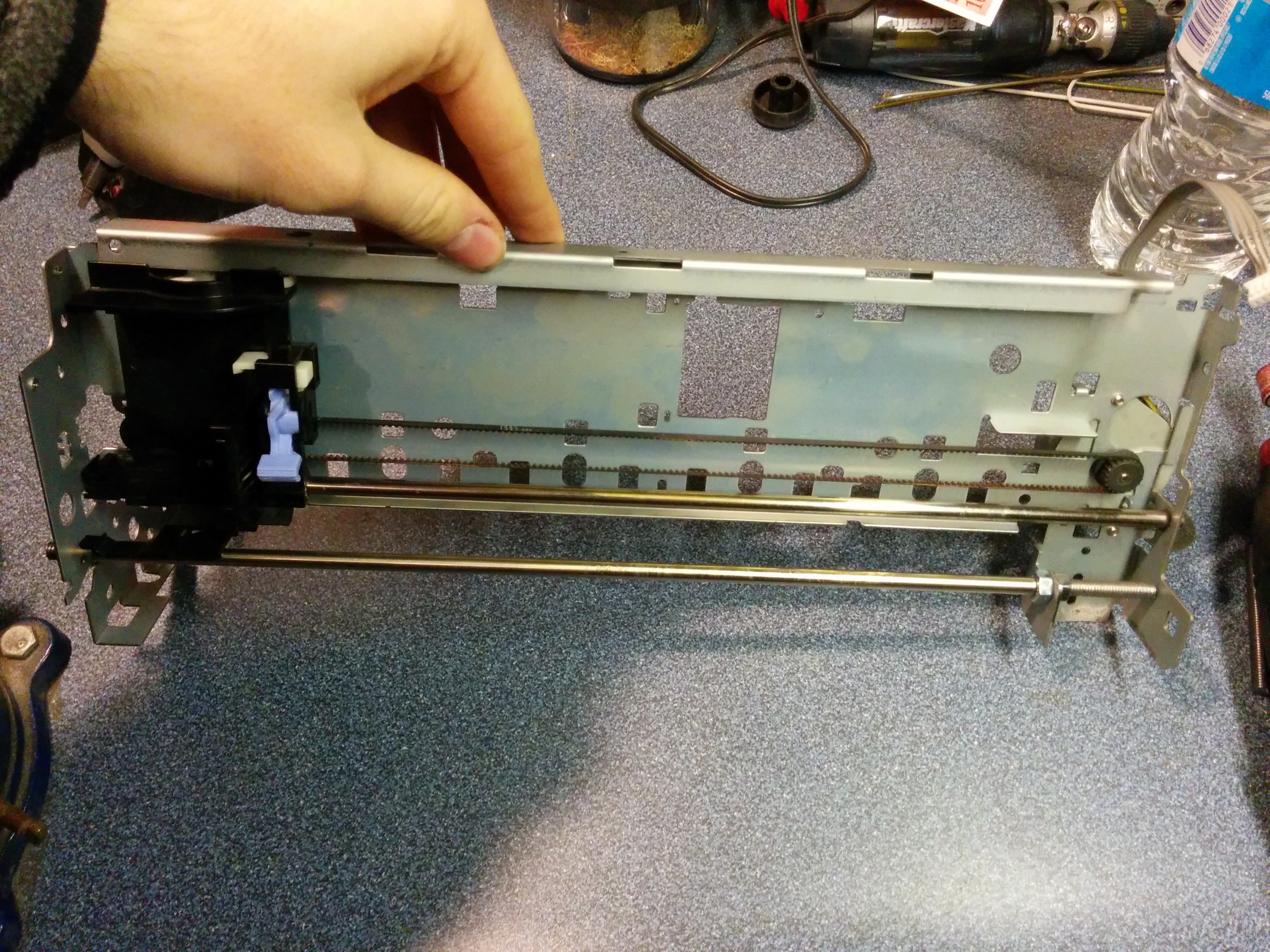
The next step was to cut threads into the rod, using an M6 die and some WD-40 as cutting oil (I didn't have anything better lying around). 3 nuts later, and I had a second rail (though no slider for it yet). I finished off by cutting the rail to length (so it wouldn't be sticking out) and sanding off some of the pointy edges I created while removing the protruding bits before.
The end result looks like this:
The next step is to make the slider, which I'm going to be cutting out of a large piece of plastic that once formed the end cap of a plotter (large-format printer), which I couldn't salvage any interesting parts from because someone got to them before I did.
Discussions
Become a Hackaday.io Member
Create an account to leave a comment. Already have an account? Log In.