Close
0%
0%

BitMasher

Portable lo-fi music sequencer

Similar projects worth following
The BitMasher is going to be a portable lo-fi music sequencer built around the Trinket Pro; it will have a minimal but functional interface that will allow to create multi-track patterns as well as to arrange such patterns to create a song.
  • 1 × Adafruit Pro Trinket - 3.3V 12MHz
  • 1 × SparkFun Micro OLED Breakout To display a basic menu and information
  • 1 × Adafruit Trellis Monochrome Driver PCB for 4x4 Keypad & 3mm LEDs The main input interface used in the various edit modes
  • 16 × Green LEDs 3mm To provide visual feedback during playback
  • 1 × Adafruit Silicone Elastomer 4x4 Button Keypad - for 3mm LEDs Pushy buttons

View all 15 components

  • PCB Layout second revision

    Michele Perla01/09/2015 at 11:58 0 comments

    Hello there,

    I just wanted to let you all know that I'm currently working on the second revision of the PCB; I have to fix a few things, all related to difficulties in properly soldering the board without the proper tools (read: missing reflow station or oven). I'm actually modifying the DFN/QFN packages so to have longer pads and exposed bottom layer pads to properly solder the heatsink pad under the chips. I'm also evaluating the idea of detaching the power section and the USB section of the circuit into a separate board, sort of a USB serial/LiPo charger/Intelligent power switch , three-in-one functional board; I really think this could be really useful for a lot of battery powered applications that need easy USB communication. Of course this may force me to have two separate boards, one for power and the other to break out the connections of the other devices.

    In the meantime, I'm also evaluating different options for implementing a working version of the DDS routine; running at 16 KHz, the interrupt routine has to process 8 tracks in less 750 clock cycles, and I have to deal with monitor and Trellis update. That's tight. I think I gotta make some math.

    Stay tuned,

    Mick

  • The end is nigh!

    Michele Perla01/03/2015 at 19:57 0 comments

    Hey there,

    this is the last day of the contest and the last hours of work for me on this project. Take a look at the demo video of what I could accomplish in a month:

    The current features are:

    Function generator (sine,square,tri,saw) with +/- 1 octave fine tuning and 4 concurrent samples playback from Flash ROM.

    To sum things up, I failed for a number of reasons:

    1) I couldn't fit even a quarter of the features I wanted to implement; the interrupt routine takes too much time to return when streaming samples from the ROM and therefore it slows things down (you can hear the frequency shift down when triggering the samples while the function generator runs)

    2)I could not assemble a PCB; it turns out that DFN package is not easy to solder, especially if you do not leave any room on the traces to put the iron on... I'll try to run a second version of the board with longer pads to better reach them.

    I learned a lot of things: pressure can make you work a lot, even when you have no time and even if that time is not enough anyway. I had a blast during the last month trying to do everything for this project in time, and I now know more about SMD PCB layout process that could help me with future projects for sure.

    Thanks Hackaday for the great opportunity.

    Cheers,

    Mick

  • Working during holidays -> stress -> mistakes (documenting today's fail)

    Michele Perla12/31/2014 at 00:54 0 comments

    Hello there,

    I just returned from my hometown, during these 4 days off from Rome I had the time to program something while waiting for the boards and for the enclosure delivery. I got everything on breadboard in order to simulate what the final PCB should do; it includes power control lines, serial communication via external USB-to-Serial converter, 5-way tactile switch w/ mux, and dual channel headphones amplifier in Sallen-Key topology to cut off "all" the nasty sampling stuff. Here's the breadboard setup, in the picture you can also read a test menu on the OLED, right now pressing left or right changes wave sound (sine, tri, saw, square, stair), pressing up or down changes frequency (not yet notes frequencies, it just changes by one the increment rate of the index used to read the tables, so it plays all the natural harmonics of 61 Hz (15.625/256 = 61 Hz)):

    First thing: I had to start program way back; working all day long was a big drawback from this and I spent so much time worrying about putting everything together for the final round that I actually forgot to focus on what should be put together in the first place.

    I'm saying so because I'm very behind schedule and the sequencer code is not yet up.

    I actually got samples playing, and that's a good thing; I also made a small Java app and sketch to stream a few WAV samples (max length 65535 bytes) to the ROM, the Java app takes the file, tells the Trinket Pro how many bytes it contains, then the Trinket Pro writes this length (two bytes) in a known address (the list starts at the beginning of the ROM), along with the address at which the sample is going to be written (4 bytes even though the ROM accepts 24 bits max addresses), and finally the app streams the whole file on the Serial port and the Trinket writes such stream at the specified address; the next file is written after the previous and so on (that is the samples data is contiguous); unfortunately, I think I'm encountering some writing issues because when I try to read such addresses I get some sound glitches; the first written sample is good, the other though are not; he oscilloscope shows that sometimes the output stays high (when you erase the ROM it is put as 0xFF) but I could clearly hear parts of the other samples during the glitches. I may want to dump the ROM and read it as a WAV file to see what's happening.

    I also just found out that when a LED on the Trellis is on, a nasty hum goes back into the audio amp surely due to LEDs PWM frequency going back on the power supply. That is not good, but it may be attenuated naturally when putting everything on the PCB (no tangled jumpers and ground plane = good).

    Other issue: I TOTALLY forgot to add elongated pads for the very small packages (read: DFN). This has led to trying to solder 3 (THREE!) boards with nasty result, the worst being burned and lifted traces due to overheating (that is me trying to heat those little dabs on the DFN package sides to let some solder flow beneath it). The worst thing is that I actually screwed up a few boards before the one I thought could have been the final one, so I "may" have ran out of a few parts; I'll try to desolder the necessary parts and start over even though I already know it may be just a waste of time (and patience); I might as well send an "enhanced" board to fab altogether and wait for it...Here's a picture of the board:

    Here you can see the first screw-up, that is another trace lifted up and I had to solder a jumper to an inductor. In the next photo you can see the multiple screw-up in one take, that is the DFN traces for the LTC2955:

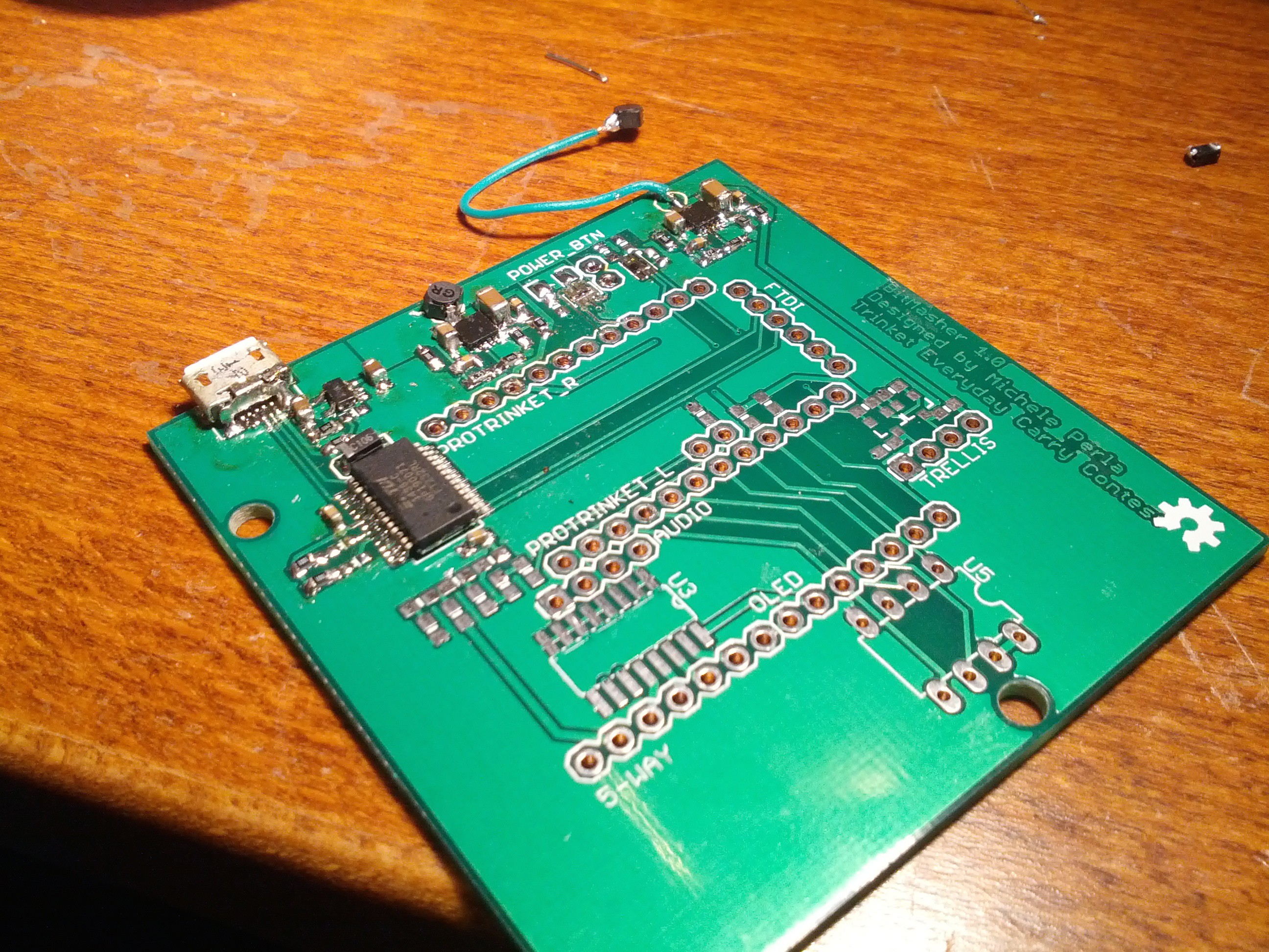
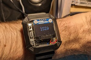
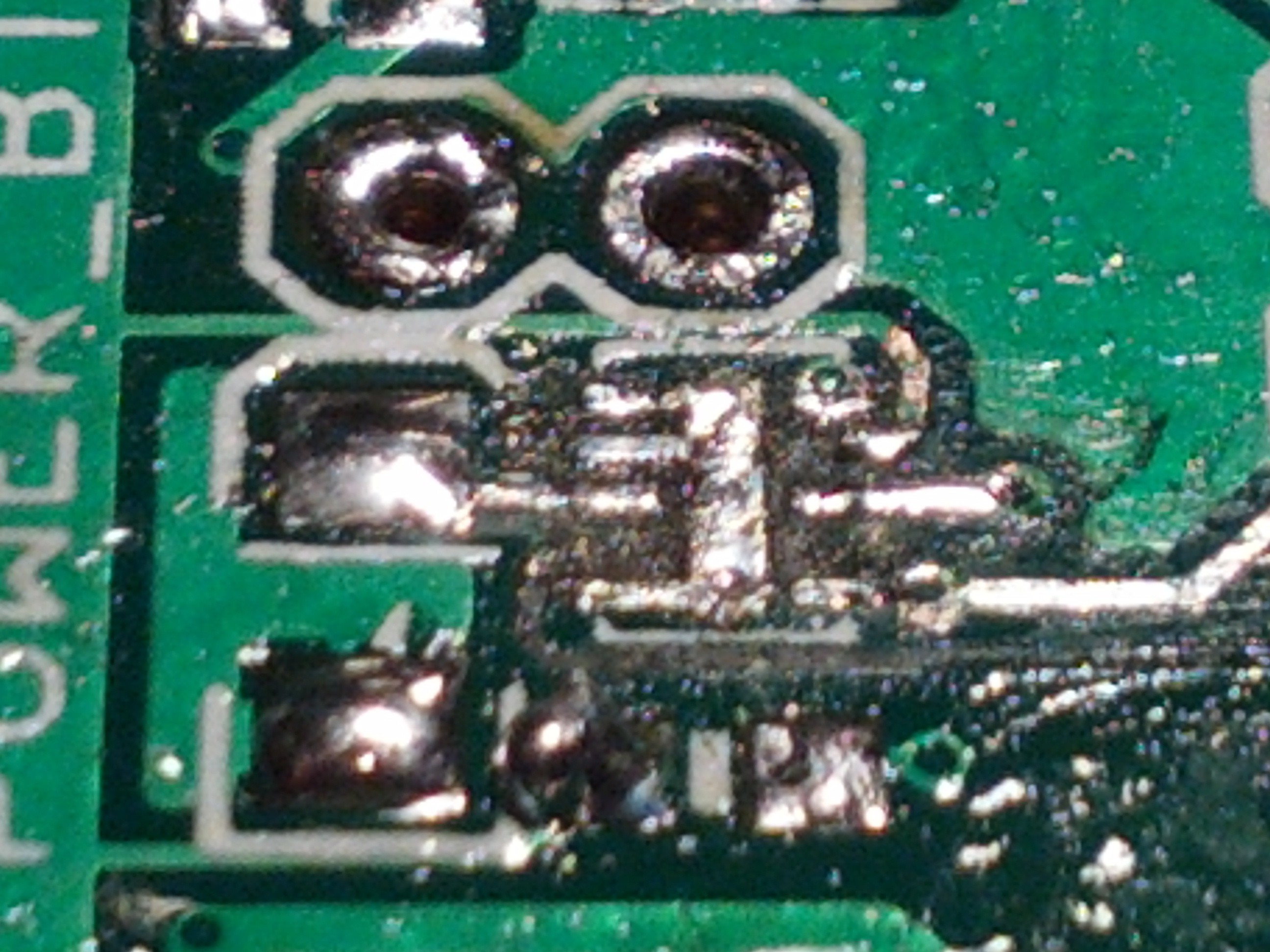
    Long story short: today I've failed hard my friends. I wanted to take a finished board with me for my new year's holidays (yep, I'm going out again) so to focus on programming, but I'm back to this:
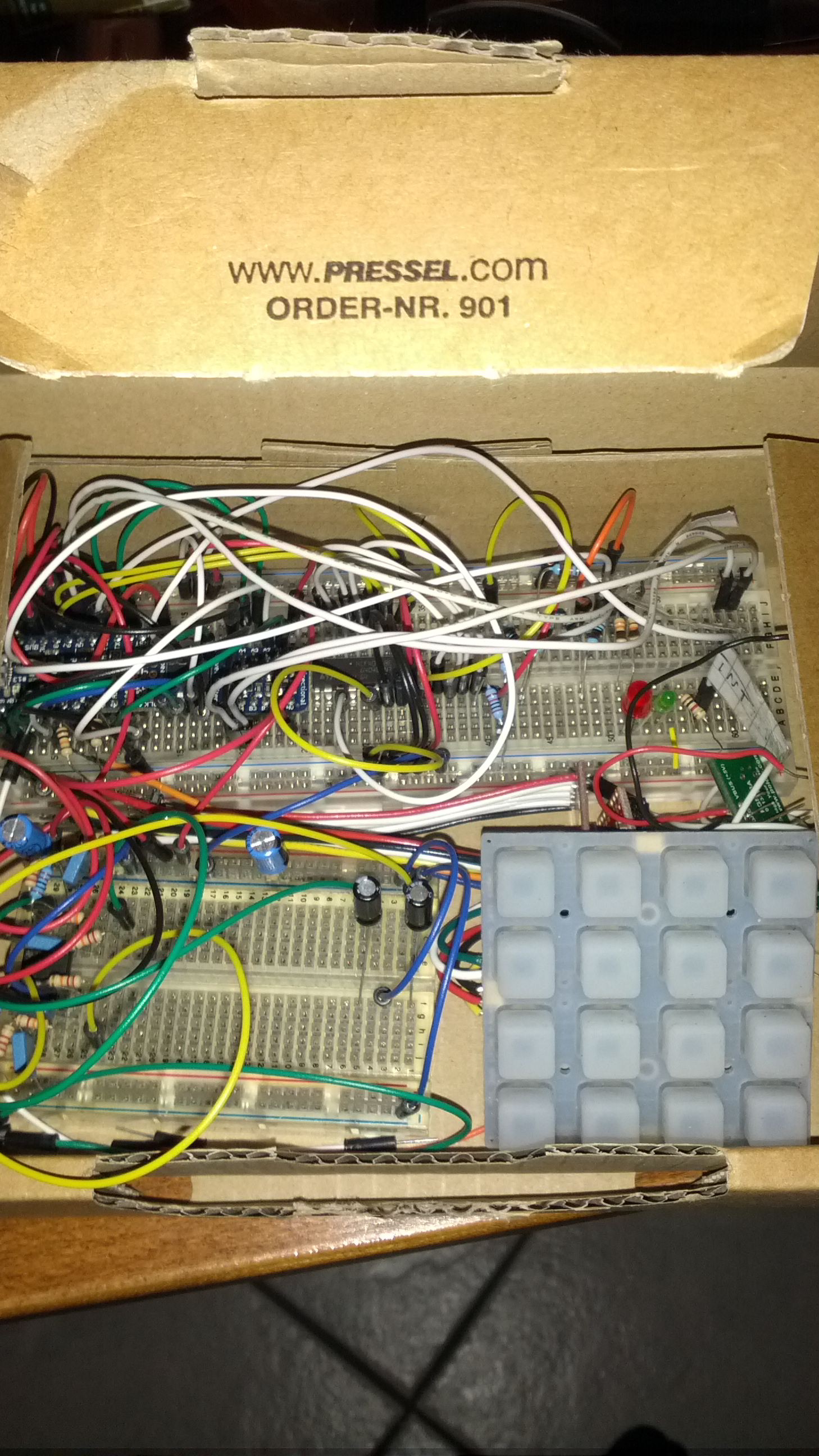
    The funny thing is that I also forgot to take the headphone plug with me because I was trying if it fitted the 3D printed enclosure but I was in a rush to pack up before leaving for a few days......

    Read more »

  • Preparation finished + 3D printed enclosure delays

    Michele Perla12/22/2014 at 16:51 0 comments

    Hey there,

    A few updates on the status of the project:

    I finished preparation phase for the project, the schematic and layout have been polished and reviewed, and the PCBs are already shipping from Shenzen, Public Rep. of China; Smart Prototyping has been my choice because they are the only cheap manufacturers that offer 24 H turnaround time and overtime for shipping on weekends, I should receive the boards in a couple days.

    In the meantime, I received all the components (ICs, resistors, capacitors, USB micro connectors etc) that will populate the boards as soon as I come back from my holidays (December 28th). I also received the 3V Pro Trinket and a 3V-to-5V logic converter to hook up the Trinket Pro with all the mandatory components at the same time, that is OLED, ROM, tactile switch and Trellis (it needs the 3-to-5V conversion). I ended up only putting direct connection to the two PWM pins on the PCB, I didn't have the time to properly test a filter+headphone amp, but I at least put an headphone jack connector hole on the enclosure; if I don't have the time to do a proper headphone amp (single supply I hate you) I'll at least try to filter the PWM a bit for line-output

    My plans for this week are to start (FINALLY!) putting together all the pieces of the somewhat huge puzzle that is this project; I'm actually testing on breadboard all the hardware I currently have using the connections as reported on the schematic, setting Chip Selects on Analog Pins, modding the SPI devices libraries to handle that, simulating interrupt and command pins using jumpers to implement low battery conditions-power on-power off sequencing; then I will dig my old code and get the synth and the sequencer up and running; I'll first fly low and test 2 concurrent sample tracks and 2 synth tracks, while also converting everything to fixed point arithmetic (my old code is using floating point, not fast at all). I also have to organize a memory map to organize storage of Songs, Patterns, Tracks, and Samples; I may want to implement a fixed addresses memory section to hold the former three, while the samples may have variable (but limited maximum) length, the idea for samples conversion is that the 8-bit audio will be preceded by a header storing a short name and a length value, and there will be a list that contains the addresses of the currently stored samples. For test purposes, I will hold test samples in program memory and write them to ROM, then access the ROM for playback; when I'll have the Serial conversion working I'll store the samples directly in ROM, but that will come later in development as I have to implement a little Java application to do so (get 8 bit 16KHz WAV file, start connection with BitMasher, transfer data ) which will probably only have a "dump everything" option to copy the ROM content and erase it.

    Regarding the enclosure: I managed to cut a small timeframe for it and I finished it yesterday evening, so I had to send it for print outside Rome; luckily this store is only closed from December 25th to 28th, so they'll probably print everything out today and send it with "really-urgent-delivery" tomorrow. Cross fingers!

    Here's the final enclosure (I opted for black everything, grey sides):

    This enclosure here is derived from the Trellis Box and it's the first 3D model I make in a lot of years (10+) and it's the very first 3D model I print, so I really hope that I didn't mess with support frames heights and other stuff :S

    Now, it's time for me to go home as my work shift is ending in a few minutes and I gotta take a train. I'll try to post more details this night or tomorrow morning.

    As always, Cheers.

    Mick

  • Finished schematic + parts ordered (2nd batch of stuff)

    Michele Perla12/15/2014 at 15:39 0 comments

    Hey there,

    I just finished polishing the schematic, correcting passives packages and ordering all the parts that will connect the guts of the BitMasher.

    I got a major change to the project, that is I could not fit multiple 1-bit audio outputs as I originally intended because I ended up using all the pins to implement power-saving features; so, I'll be using two PWM pins to provide dual-mono output, hopefully stereo output if fixed point arithmetic is fast enough to handle panning.

    Let's take a look at the schematic (which has been divided in sub-sheets for ease of understanding):

    In the upper-left section you can see the Trinket Pro and the connections needed to run everything; the obvious and fixed breakouts are AUDIO_L/R which are Timer1's pins, SPI MOSI/MISO/SCK, shared by OLED and ROM, and I2C SDA/SCL lines, shared by Trellis and Fuel Gauge (seen in the following part of the schematic),the TX/RX couple for the FT232RL USB to Serial converter (to add Optiboot+Serial support), and the !INT line which is an interrupt line tied to pin D3, used by the LTC2995 to raise an interrupt when the power button is pressed; then we have not fixed lines (read: lines that I have yet to decide to which pin should be connected for ease of PCB layout), which are the two SPI Chip Selects, the !KILL line which is pulled low to cut-off power to the 3.3 V Regulator, the 5VEN line which is used to enable the 5 V Regulator, the MUX_A/B/OUT and the RIGHT lines, which are used as a gimmick to read the 5 pushbuttons of the 5 way switch using 4 pins (3 to mux the first 4 switches, 1 is tied directly to the last analog-only pin).

    The !INT/!KILL lines are a very useful addition to the project as they allow the device to shutdown itself; its main use is to provide a graceful power-up and power-down sequence; the device has in fact the time to run a few checks before actually starting up or shutting down; at power-up, it will check if there is enough battery charge to power up everything and will show a "LOW BATTERY" message if that's not the case; at power-down it may show a "SAVE?" option before actually shutting down, or it can show again a "LOW BATTERY" warning when it needs to be charged and save something instead of just dying. The 5VEN line is very useful to allow such power-saving options; for example, when dying, the device can shutdown the Trellis and Audio output (80-85% of total power consumption) to safely perform some saving routines and then shutdown correctly.

    I may need to monitor the USB 5V via the Trinket Pro to check if the device is currently attached to a USB port for charging, but I ran out of pins so I may have to resort to a 2-bit R2R DAC on one of the analog only pins, one bit will be the 5V USB input, the other will be 3.3V from one of the 5-way switches, so to understand correctly whether I only have a button press (low-level), only 5 V from USB (mid-level), and both (high-level). On second thought, I'll probably use the 3.3V LDO of the FT232RL to provide a 3.3 V signal to the Trinket Pro to understand if it is currently powered via USB.

    This is actually mandatory because I don't want the device to be usable when powered via USB other than for data transfer because if I'd plug the device and bypass the battery for power, I could power everything up but max. power consumption will not leave any juice to charge the battery; the only way is to limit power consumption when charging via USB, right now the setup is 400 mA for charging and 100mA for trinket-rom-oled-ft232 together. The device will run a few checks at startup to see if it is powered from USB charging and ready to transfer, charging only, or battery powered.

    In the meantime, I STILL have to define a proper op-amp configuration for the audio output; I have to bias the op-amp to 2.5V (that is add 0.85 V to the already present 1.65 V bias of the PWM outputs) and filter the 16 KHz PWM frequency, and also I have to ac-couple the output signal to the headphones to finally remove the...

    Read more »

  • Automatic power on/off switch

    Michele Perla12/10/2014 at 11:33 0 comments

    Quick update,

    a bit of google-fu took me to the following page:

    http://forum.allaboutcircuits.com/threads/auto-off-switch.27626/

    I think I have found a neat solution to my power on/off switch:

    My version will have the line that goes to VDD connected to the 3.3v converter ENABLE , that will in turn power the Trinket Pro, which will then pull high the BS108G gate to keep everything powered or pull it down for auto shut-off, while monitoring the line currently connected to pin 4 of the picaxe in the schematic to monitor for a turn-off signal.


    SWEET!

    Cheers,

    Mick

    EDIT: Both transistors are reaching End-of-life and are not available anymore for purchase... let's look for alternative transistors.

  • ROM/OLED power on/off available + ROM/OLED test video

    Michele Perla12/10/2014 at 10:24 0 comments

    Hey there!

    Before reviewing the schematic I had a look at the datasheets of both the SSD1306 OLED controller and the W25Q80BV Flash ROM, and both have a sleep mode/power-down mode. Hoorray! This means that the current power configuration should work to power Trinket Pro, OLED and ROM when the device is in the following states:

    • Turned on with low battery (Trinket and OLED only, to show "low battery message"), current should be under 30 mA;
    • Turned on with low battery while charging (Trinket/OLED/ROM working to enable data transfer via USB-to-Serial, total current should be under 100 mA, the remaining 400 mA of the USB will be used to charge battery; 3.3V regulator should also switch to power via USB rather than battery to provide maximum charge current to the battery (will the schottky diode work like on the Trinket Pro regulator)
    • Turned on with very low battery and not charging, only the Trinket should power up to check battery status and turn off

    I still have to find a way to let the Trinket Pro shutdown itself; probably a pin that pulls low the ENABLE pin of its regulator won't work alone, but maybe pulling it low for some time while charging a capacitor should work?

    While I find the perfect solution to this feature imlpementation, take a look at the OLED+ROM test that I performed on the Teensy 3.0; I'm using the Teensy 3.0 because that's the only 3.3V compatible board that I had lying around my house; I'll soon get a Trinket Pro 3.3V.

    Cheers,

    Mick

  • Designing board = implementation issues!

    Michele Perla12/09/2014 at 23:07 0 comments

    Hello there,

    I'm thinking and rethinking the design of the board that will host all the ready-made pieces, and I'm facing a multitude of issues, related to power:

    • How do I get both 5 and 3.3 V from the battery while charging it via USB?
    • Can I selectively turn on parts to consume less?
    • How much power will everything consume in worst case?
    • Can I gracely turn off the circuits when battery power is low?
    • Can I show a "battery dead" screen on monitor without further killing the battery?

    I still have to answer a few of these questions; what I got right now is that it will surely be easier to deal with a 3.3 V Trinket so to have two batttery-fueled power zones:

    • 3.3 V : Trinket Pro / Micro OLED / 1 MB ROM
    • 5 V : Trellis / Audio Amp

    In this configuration I can right now shutdown Trellis+Amp by disabling the 5 V dedicated step-up converter, since Trellis will eat 320 mA alone with all LEDs on and Audio Amp may be eating other 80 mA, that's 400 mA total.

    I still got to find a way to turn on the Trinket Pro first, then check for battery status, and eventually turn on OLED/ROM to display/read something, and even further turn on Trellis/Audio Amp for full functionality. I should implement a fixed regulator that powers the Trinket, possibly attaching it to the battery may work, then the Trinket will selectively turn on a 3.3 V regulator or a 5 V regulator or both. Gotta see if OLED/ROM library or chips support a power-down mode via software rather than brute-forcing it via regulator shut-down.

    I'd like that when powered via USB, the BitMasher may only turn on Trinket Pro, OLED, ROM to leave all the juice to recharge battery; this will limit the USB-powered functionality to charge and to data transfer, but that seems fair to me.

    Take a look at the first revision of the power section schematic for reference:


    I'll keep working on this part until Sunday at the very last, I got to move on the software side asap!

    Cheers,

    Mick

  • Main parts delivered, plus good news

    Michele Perla12/03/2014 at 20:33 0 comments

    Hello there,

    The main parts that will compose the project have arrived! See them in all their glory here below!

    You can see a few random buttons (just in case I might need them) on the up-right corner and the model of the op-amp (in the left side) that I may use for the headphones amp, a TLV2462 rated for current outputs of up to 80 mA, and it's rail to rail! I also got some TL072-074 chips that will probably be used for the mixer part, which is mandatory to blend the 1-bit outputs with the PWM outputs together.

    Other than for the charger/step-up/monitor circuit, I was concerned on where to print the 3D case for this beauty, but LUCKY ME! I found www.3dhubs.com and a new world opened in front of me, in fact I found some pretty good places (or "hubs") that have high quality 3D printers and for cheap here in Rome!

    More on the case design: I will start from the Trellis enclosure design took by Adafruit and enlarge it and cut a few extra holes to fit the display, the 5-way joystick, the power switch, the headphones and line-out jack; probably I'll also reduce its height, so to better fit in a pocket.

    I'm starting work on the charger circuit now, then I'll source its parts along with a 2000 mA 3.7 LiPo battery (the cheapest I could find on Farnell); I hope that they have the exact parts of the Sparkfun designs...

    See you next update!

    Mick

  • Plug-everything-here main PCB w/ battery management

    Michele Perla12/03/2014 at 00:37 0 comments

    Hey there,

    After a whole day of scratching my head looking for the perfect charging circuit + step up + battery monitor online (while working 9 to 6), I decided to brew my own.

    The circuits that I liked the most are:

    Sparkfun LiPo charger basic : https://www.sparkfun.com/products/10401

    Sparkfun Fuel Gauge : https://www.sparkfun.com/products/10617

    Pololu Step-Up 5 V voltage regulator : http://www.pololu.com/product/2115

    Adding these boards together should work pretty well for my needs (which are steady 5 V @ I >=300 mA, fast charge rate @ 500 mA, low battery sensing), but them together with the battery cost more than half of what I've already spent of hardware for this project, take so much room, and I really don't want another USB port on my device just for charging it... anyway space is what concerns me most right now; luckily, these circuits are all so small and only need a few passives to work, that putting them together on a PCB will be a piece of cake. And hey, the first two have free schematics online, thanks Sparkfun!

    So, as soon as I have further time to work on the project, I will la down a PCB for this module while the other components get delivered.

    As soon as I have the components, I will also evaluate the option of a main PCB that may actually host the battery management circuit, something like an "undershield" for the Pro Trinket; this may also help with keeping together all the small modules that are not provided with mounting holes.

    See you next time!

    Mick

View all 12 project logs

  • 1
    Step 1

    Send the PCB to fab house (or print your own if you can handle 2 layers with vias)

  • 2
    Step 2

    While waiting for the PCBs, order all the components (Mouser and Farnell have most of the ICs/passives, while Adafruit and Sparkfun should cover the rest)

  • 3
    Step 3

    Get all the source (schematic, board layout, code, case design) from the Google Drive link on the left side of the project page

View all 6 instructions

Enjoy this project?

Share

Discussions

Similar Projects

Does this project spark your interest?

Become a member to follow this project and never miss any updates