 Michele Perla
Hey there,
I just finished polishing the schematic, correcting passives packages and ordering all the parts that will connect the guts of the BitMasher.
I got a major change to the project, that is I could not fit multiple 1-bit audio outputs as I originally intended because I ended up using all the pins to implement power-saving features; so, I'll be using two PWM pins to provide dual-mono output, hopefully stereo output if fixed point arithmetic is fast enough to handle panning.
Let's take a look at the schematic (which has been divided in sub-sheets for ease of understanding):
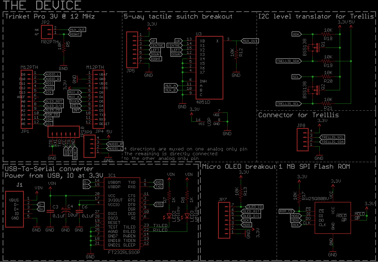
In the upper-left section you can see the Trinket Pro and the connections needed to run everything; the obvious and fixed breakouts are AUDIO_L/R which are Timer1's pins, SPI MOSI/MISO/SCK, shared by OLED and ROM, and I2C SDA/SCL lines, shared by Trellis and Fuel Gauge (seen in the following part of the schematic),the TX/RX couple for the FT232RL USB to Serial converter (to add Optiboot+Serial support), and the !INT line which is an interrupt line tied to pin D3, used by the LTC2995 to raise an interrupt when the power button is pressed; then we have not fixed lines (read: lines that I have yet to decide to which pin should be connected for ease of PCB layout), which are the two SPI Chip Selects, the !KILL line which is pulled low to cut-off power to the 3.3 V Regulator, the 5VEN line which is used to enable the 5 V Regulator, the MUX_A/B/OUT and the RIGHT lines, which are used as a gimmick to read the 5 pushbuttons of the 5 way switch using 4 pins (3 to mux the first 4 switches, 1 is tied directly to the last analog-only pin).
The !INT/!KILL lines are a very useful addition to the project as they allow the device to shutdown itself; its main use is to provide a graceful power-up and power-down sequence; the device has in fact the time to run a few checks before actually starting up or shutting down; at power-up, it will check if there is enough battery charge to power up everything and will show a "LOW BATTERY" message if that's not the case; at power-down it may show a "SAVE?" option before actually shutting down, or it can show again a "LOW BATTERY" warning when it needs to be charged and save something instead of just dying. The 5VEN line is very useful to allow such power-saving options; for example, when dying, the device can shutdown the Trellis and Audio output (80-85% of total power consumption) to safely perform some saving routines and then shutdown correctly.
I may need to monitor the USB 5V via the Trinket Pro to check if the device is currently attached to a USB port for charging, but I ran out of pins so I may have to resort to a 2-bit R2R DAC on one of the analog only pins, one bit will be the 5V USB input, the other will be 3.3V from one of the 5-way switches, so to understand correctly whether I only have a button press (low-level), only 5 V from USB (mid-level), and both (high-level). On second thought, I'll probably use the 3.3V LDO of the FT232RL to provide a 3.3 V signal to the Trinket Pro to understand if it is currently powered via USB.
This is actually mandatory because I don't want the device to be usable when powered via USB other than for data transfer because if I'd plug the device and bypass the battery for power, I could power everything up but max. power consumption will not leave any juice to charge the battery; the only way is to limit power consumption when charging via USB, right now the setup is 400 mA for charging and 100mA for trinket-rom-oled-ft232 together. The device will run a few checks at startup to see if it is powered from USB charging and ready to transfer, charging only, or battery powered.
In the meantime, I STILL have to define a proper op-amp configuration for the audio output; I have to bias the op-amp to 2.5V (that is add 0.85 V to the already present 1.65 V bias of the PWM outputs) and filter the 16 KHz PWM frequency, and also I have to ac-couple the output signal to the headphones to finally remove the bias. I'm currently testing a 1.1 gain inverting low-pass topology, 1.01 just to avoid any possible stability loss. I added a 4 pin thru-hole header so that I can add the small op-amp circuit later and eventually assemble it on a protoboard (I'm going to order the PCB as soon as I finish the layout).
Now for the power section:
 Except for the LTC2995 breakout, everything is took from Sparkfun designs, therefore the power section is Creative Commons licensed 3.0 as their products, linked in the "link" section of this project. No fuss, there's a 400 mA set battery charger, a fuel gauge that talks via I2C, a 3.3V and a 5V regulator powered from the battery, and a power on/off switch controller with interrupt signalling and that enables the 3.3V regulator, while the 5V regulator is directly enabled/disabled via the Trinket.
For the software side, I'm going to take a few parts of code from my previous attempts at DDS and sequencing, with a little modifications. I want to add buffers for each track so to precalculate upcoming samples instead of calculating in realtime (sample by sample). I'd like to reduce the notes updating routines to something like 60 Hz, just like the old consoles used to do, that is sync'd to the monitor update frequencies (horizontal sync used as sampling rate, vertical sync used as frame/update rate). I may actually up the PWM frequency up to 16384 Hz so to have 1/256th of the sampling frequency at 64 Hz (that is I can use an 8 bit unsigned counter and check for it being 0 to signal a "frame" update). I cannot tell much now because I gotta be honest, I still have to get my hands on REAL code. I've just been fiddling around with tests at the moment.
So, let's finish the layout and send the PCB to fab; while they ship, I'll code the hell out!
See ya next time (and soon),
Mick
Discussions
Become a Hackaday.io Member
Create an account to leave a comment. Already have an account? Log In.