 Bud Bennett
I received 3rd pass PCBs from OSH Park some time ago, but haven't had time or interest to get them populated and tested until today. The revelations from testing the single battery mag switch circuits made me reconsider a couple component choices for this project. I changed two things: C2 was reduced from 6.8µF to 0.1µF to reduce any possible transient spike when plugging a battery into either input, and I used a different hall-effect switch that has poorer sensitivity (and improved interference) as well as a CMOS output and active high function. The latest schematic is shown in the project details.
Measurements:
Off-state current dropped to 34µA @ 8.4V (35.7µA @ 12.6V) which is an improvement over the second pass circuit. This is due to lower current drain from the hall-effect switch. The current seemed more stable also -- not as much jumping around.
The resistance of the N-channel FET switches got better. With 3.6A applied, I measured 42.6mV across the N-channel switch. This is 11.8mΩ. Not a big improvement, but an improvement nonetheless.
The resistance of the P-channel FET switches also got marginally better. I measured 7mΩ.
With these new numbers I calculate that the power dissipation of the circuit with 4A of load current is 0.3W if a single battery is carrying the load. The dissipation rises to 0.67W for a 6A load. These are pretty reasonable numbers.
Input Transient:
I'm a bit nervous about input voltage transients created when a battery is plugged into the circuit. Simulation indicated that I should replace the 6.8µF, C2, for a 0.1µF. The tantalum capacitor, C6, has at least 500mΩ of ESR, so it doesn't induce ringing at the input. Reducing C2 to a small value got rid of any tendency of the circuit to ring when a battery was plugged in.
I tested this with these prototypes and got the this nice waveform on the scope:
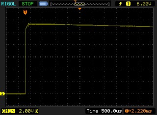
No ringing!!!
Finished with this project.
At this point the circuit is achieving all of the goals I set at the beginning. The only thing that I would improve is a higher maximum input voltage limit. The current circuit is limited by the voltage rating of C6, which is 16V. If I could find a reasonably priced 25V 47µF tantalum capacitor in a 3528 package it would allow the use of 4S LiPo batteries. But I don't think this is a very big deal. Most users of this circuit are just looking to operate their electronics at lower voltages since there is no motor. I'm done...
Discussions
Become a Hackaday.io Member
Create an account to leave a comment. Already have an account? Log In.