 Bud Bennett
It all fell apart when I took another look at how the LTC4412 was supposed to switch between the two batteries. I had simply copied the circuit from the data sheet -- a bad idea in this case. It would work pretty well if B1 was a 3S LiPo and B2 was a 2S Lipo. But if the two batteries had the same potential they would not share load current between them. What I really needed was two ideal diodes. Back to the drawing board.
I searched the internet to see if somebody made a dual ideal diode (or oring MOSFET controller, as some manufacturers call it) that satisfied my requirements of input voltage, quiescent current, and RDSon if the switches were internal to the IC. Nobody makes a dual unit unless it part of a hot swap function with a gazillion pins, or consumes 10X my current budget. So I bit the bullet and added another LTC4412 to control the B1 input. Here's the third pass schematic:
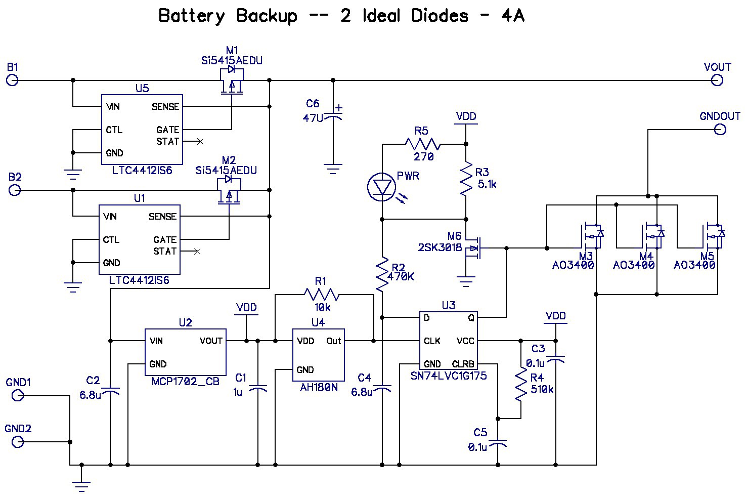
The output switch got a lot simpler after I realized that I could use an N-channel MOSFET to switch the load on and off. There is no real GND terminal in a model aircraft, so you can disconnect the load from either the positive or negative terminal. The gate drive of the output switches is only 3.3V so I put 3 AO3400 FETs in parallel to obtain the required 8-10mΩ RDSon.
I also added a LED to indicate when the circuit was supplying power to the load. I've quite a few of these 0603 LEDs in my inventory, but never remember to use them. 5mA current is pretty bright.
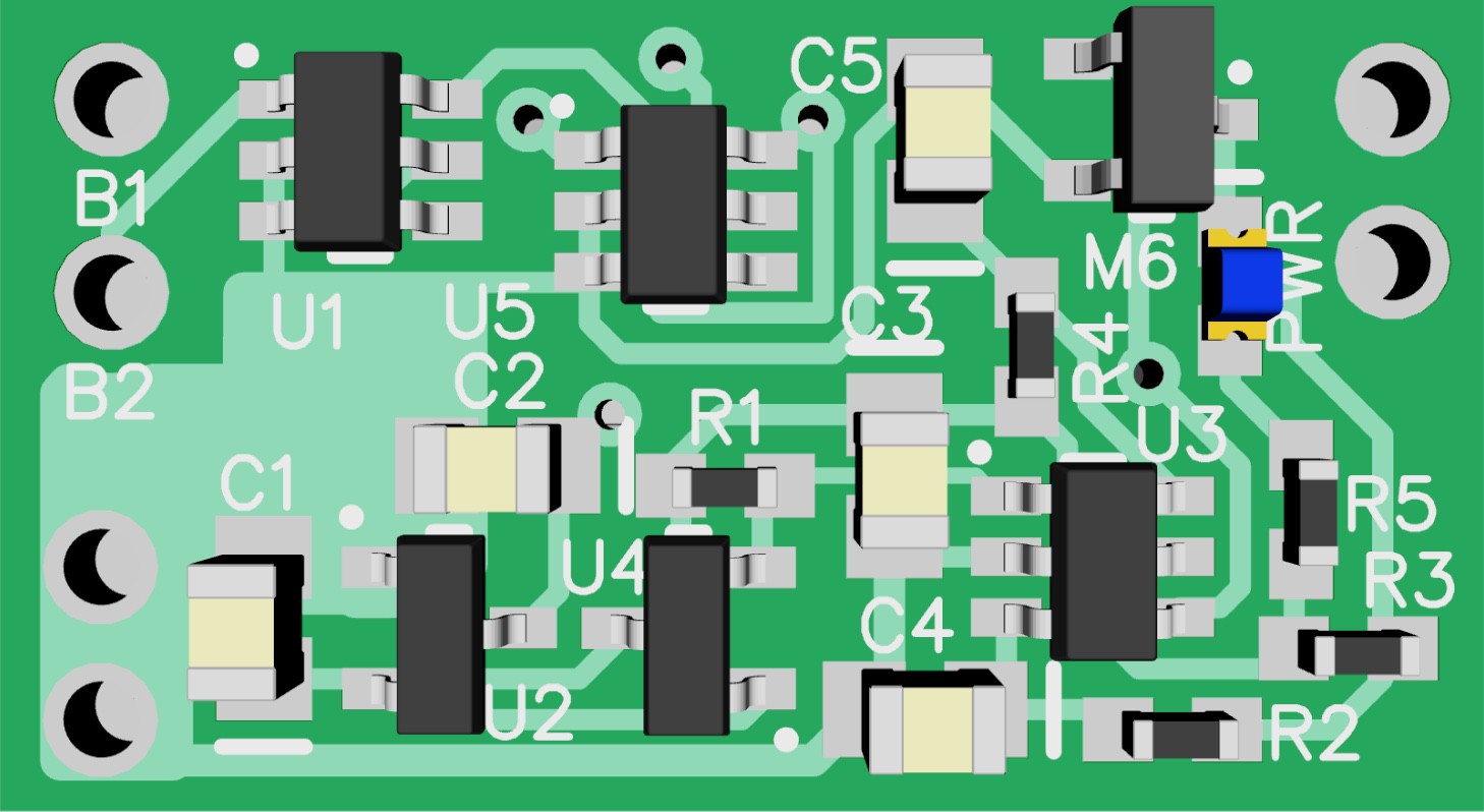
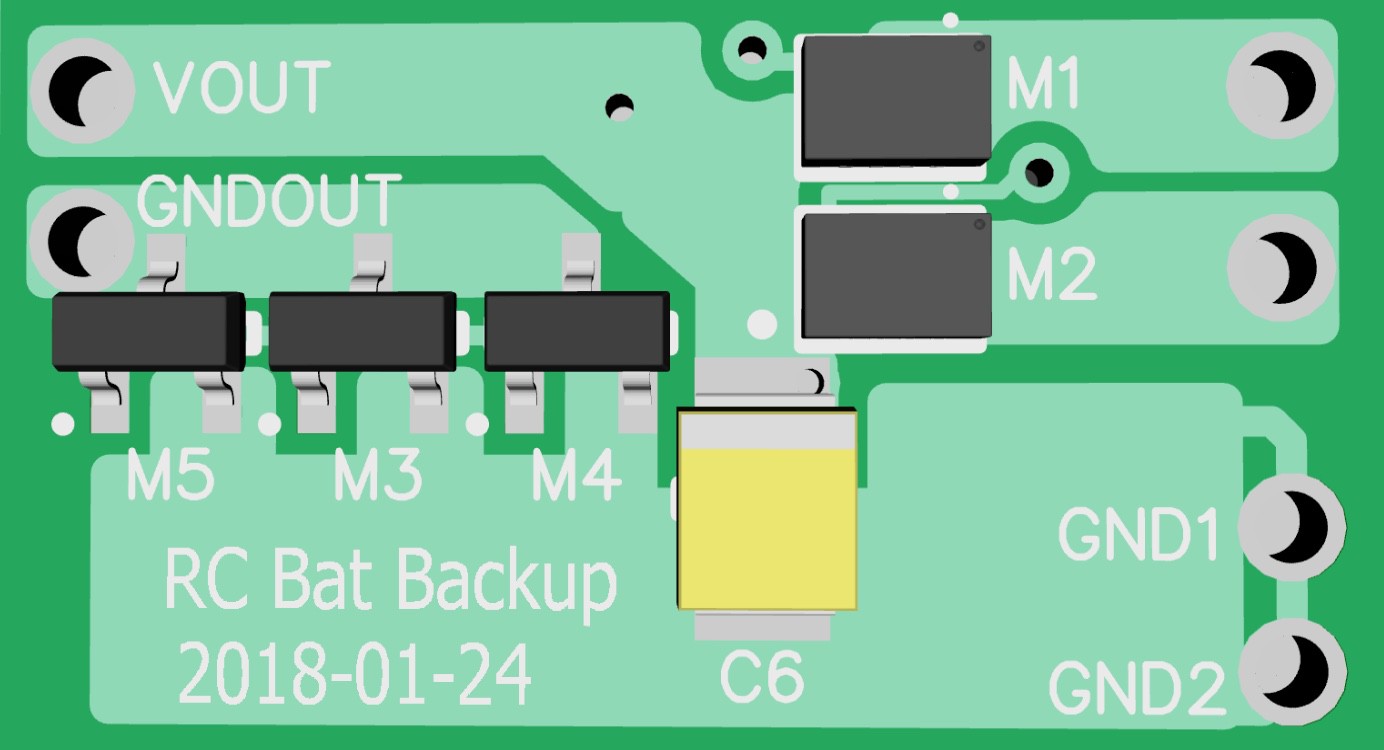
The overall circuit is quite a bit simpler, with fewer components and the resulting layout is even a bit smaller that the second pass circuit. But the cost budget is now slightly over target.
Off-state Current Budget:
U1+U5 ~25µA (no STAT pin current) -- a bit of a guess since the 4412 is only spec'd at 3.6V or 28V.
U2 = 2µA
U4 = 8µA
U3 = ??
Total ~ 35µA + U3?
Pretty close to target...depends upon what U3 Iq really is.
Layout:
Cost Estimate:
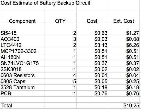
I've got an itchy trigger finger on this one. I can't see much wrong with this circuit so I might just go ahead and pull the trigger to start fab at Osh Park. If I'm wrong it will cost me only $2.30. The fab cycle for 2 oz. copper PCBs at OSH Park is about 1 month.
Discussions
Become a Hackaday.io Member
Create an account to leave a comment. Already have an account? Log In.