 Bud Bennett
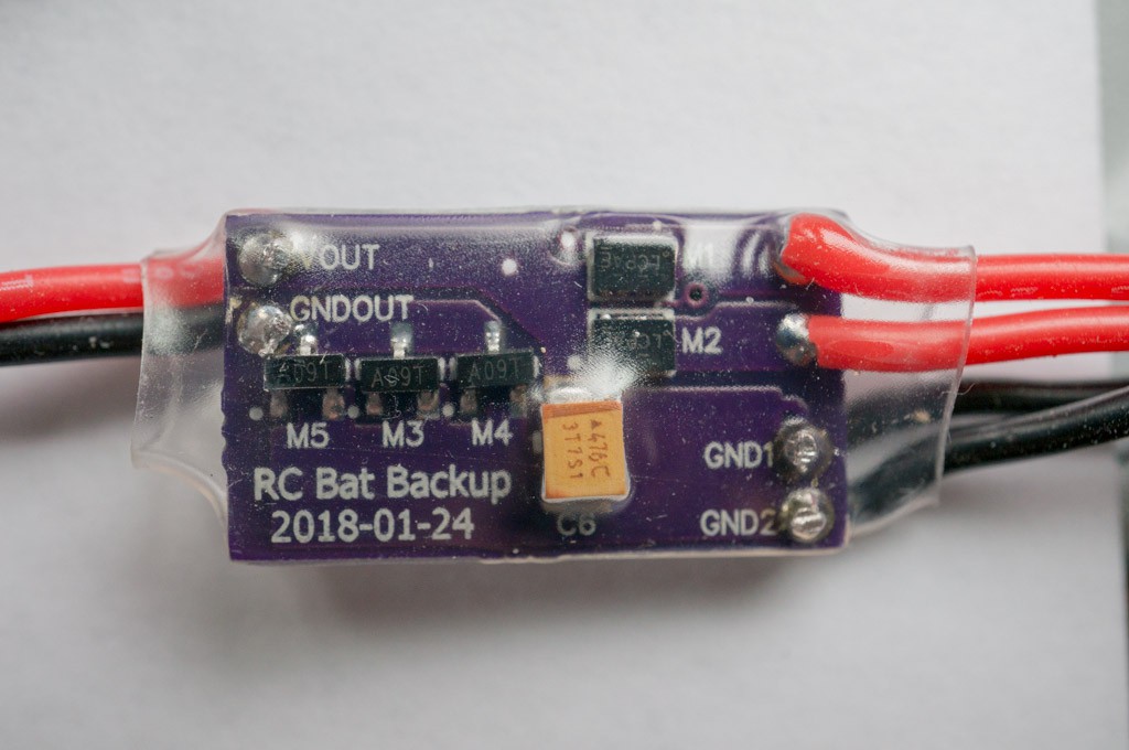
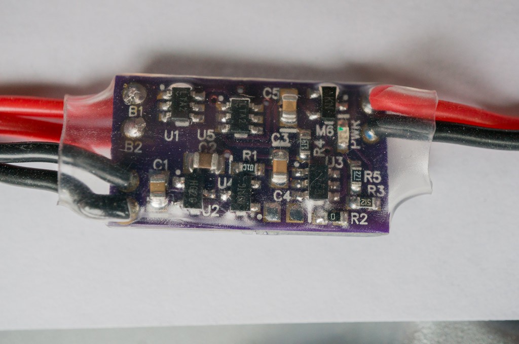
The PCBs arrived yesterday and I had a board populated by noon today. The DFL packages gave me less trouble than I expected, even though I'm not sure I got the correct values for solder mask shrinkage around the pads on that device. I also did not populate C4, and R2 is a short ( see RC magnetic switch project for details). Here's what they look like:
Second Thoughts Already:
As soon as I popped the boards out of the mailing envelope I knew that it wasn't going to be good enough. I had learned to make the critical traces that determine overall insertion loss (PCB trace resistance) as short as possible, from experience with the first prototypes of the RC Magnetic Switch project. That lesson hadn't been learned yet when I ordered PCBs for this pass. You can see how long and skinny the traces are that lead from M1 & M2 to VOUT, and also from M4-M5 to GNDOUT, and even too long from GND1 & GND2 to the sources of M4-M5. Those traces add several mΩ to the total that shouldn't be there. The goal should be to have only 1-2 squares of trace resistance in all of those critical paths -- not 4-6 squares as you can see in the photos above. The boards are pretty cheap, so I might have another go at it to see how much improvement can be had.
Measurements:
First I tested functionality. Without a load attached I connected a power supply to B1, and another power supply to B2, and varied the input voltages from 3V to 13V. The voltage at VOUT always followed the higher of the two potentials. I also tested the magnetic switch action with 3V applied to the inputs -- no problem there. Then I cranked one supply up to 12V and set the other at 4V, then I turned off the 12V source and VOUT floated nicely to 4V and stayed there. I then switched the two input sources and the result was the same. The LTC4412 is doing its job.
Quiescent Current:
With the mag switch in the off-state I measured 42µA average current into B1 = 8V, with B2 at 0V. Ditto for current into B2 = 8V with B1 = 0V. The current into the input with the lower voltage was only 0.2µA. I was shooting for <35µA of off-state current, but this is probably good enough. It will take 1.3 years to discharge a 500mAh battery.
Insertion Loss:
I connected a 2Ω cement resistor between VOUT and GNDOUT. I set both power supplies to max current limit and 8V, no load. I activated the mag switch and both power supplies dropped to 6.0V with their current limit lights active. (These power supplies are supposed to output 3A @ 36V. I'm going to have to find out why they can only output 1.5A now.) In any case, the load current is almost exactly 3A. I measured 46mV across the NCH switches, and 23-27mV across the PCH switches. This translates to 15.33mΩ for the NCH switches, and 15-16mΩ for the PCH switches, since they are sharing the current between them. This is about 50% higher than expected, but I think that the shared load current isn't large enough to force the LTC4412 out of regulating the voltage across the FET. The result is that the resistance of the FET switch appears to be larger than it really is.
I then connected two 3S LiPos to the inputs. The batteries were fully charged to 12.5V, so the switch was carrying 6A. Measured 75mV across the bottom FETs and only 24mV across the top FETs. That’s approximately 13mΩ for the bottom FETs, but I still don’t think that the top FETs are fully on yet. I changed the load current to 4.1A and got 34mV across the top FET for just one battery connected, so that’s about 8mΩ. The load resistor starts to smell funny after 30 seconds or so. With 6A and 12V it;’s dissipating 72W!! The switch dissipation is only 0.6W — I checked for heat on the board and was surprised that everything was running at nearly room temp. I can’t feel any temp rise when the load is 4A or less — the switch dissipation at 4A is only 300mW if the batteries share the load, 360mW if one battery is supplying all the current. This is probably acceptable, but it can be made better with a better layout with shorter traces.
Bottom Line:
It works, but could be better.
Discussions
Become a Hackaday.io Member
Create an account to leave a comment. Already have an account? Log In.