 Bruce Land
Video Generation
There are several very good references for understanding how TVs are controlled by a pulse sequence. I particularly liked the Stanford EE281 Handout #7 entitled "TV paint". Also very useful were Software generated video, by Rickard Gunée, Video Tutorials by Glen A. Williamson, and various excellent projects by Alberto Riccibitti. Mark Oreglia, Professor, Department of Physics at The University of Chicago and The Enrico Fermi Institute was kind enough to allow me to post a full interlaced, NTSC sync driver.
The goal is to generate non-interlaced, black and white
video,
with enough image content to be interesting as a graphics device. The
software
described here implements an NTSC-rate, non-interlaced, video signal.
For ease
of teaching, I wanted as much of the code as possible to be in C, with
litttle
or no assembler. The current version of the code is entirely in GCC,
with no assembler.
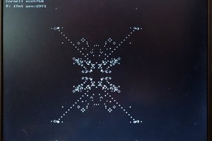
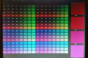
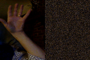
There are several versions with different horizontal and vertical
resolution. See the examples below. There are utilities for drawing
lines, points, and text, and for reading
back the screen color. The raster generation code needs to run fast to
get good
pixel density. Once the TV gets to the bottom line displayed
(ScreenBot), there is some extra time to do
computations, interact with users, or update state. All drawing must
be done
when TV scan lines are not actually being drawn to avoid visual
artifacts. Synchronization is handled by the two ISRs. Drawing is
done by writing bits (pixels) into the main screen array, while
the array is not being displayed. The drawing utilities described below write
to screen memory for you.
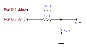
Video DAC
Two bits of a port are used to generate three video levels:
- Sync level = 0 volts
- Black level = 0.3
- White level = 1.0
The circuit shown below connects the Mega644/1284 to the TV.
Video code using the USART as a pixel shift register (On Mega1284)
The code is sets the USART into MSIPM mode (SPI master mode) which turns off start/stop bits. The USART transmit-double-buffer makes it possible to stream pixels at a uniform rate without assembler, just by writing a fairly fast loop. With a 16 MHz crystal, the pixel rate is 4 MHz. The SYNC signal is now on pin D.0 and the video on pin D.1. There are 3 versions with formats 144x150, 160x160 or 160x200, but other values are possible. This code also uses a separate timer interrupt to put the MCU to sleep so that main does not have to. The result is that application code can run faster because frame calculations do not have to be precisely timed to fit between frames.
Program Organization
The programs haveseveral parts:
- The timer1 compare-matchA ISR generates the horizontal and vertical sync. Also, on active video lines, a single line of the the raster is drawn by dumping several bytes to the video DAC as fast as possible. You should not need to modify the ISR unless you want to add a short amount of code that needs to execute 15,750 times/sec.
- The timer1 compare-matchB ISR puts the MCU to sleep just before the matchA ISR is thrown, so that entry into the matchA ISR is cycle-accurate (to avoid video jitter).
- Two big tables in flash memory containing the bitmaps for the large and small characters. Feel free to design our own characters.
- Functions which implement a few primitive graphics operations which are
nice to have:
- Draw/erase/invert a point
- Detect a point intensity in video memory
- Draw text and characters
- Draw lines
- The main function of the program. The timers are initialized and constant lines and strings are drawn. Then the program drops into a while loop which executes when the screen is not being actually refreshed by the cpu. The ISR generates sync pulses at all times. About 90 percent of the cpu is used to refresh the video display, but there is about 4 mSec between frames to update the screen content (See API below).
Video content API
void video_pt(char x, char y, char c) |
...


 Dr. Daniel L. Lau
 matseng
LOL "TVs are Cheap LCDs!"