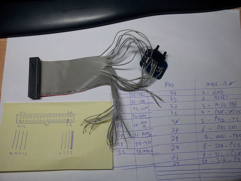
This afternoon was placed under the sign of solder.
The FM transmitter has a lot of test points but I need a way to hook them up to the Trinket. I do not want to solder wires directly to the Trinket and to the FM transmitter. I prefer to use a breadboard.
So, I need wires that can be easily soldered to the Trinket while being easy to connect and disconnect to a breadbord. I tried using jumper cables but they were difficult to solder. My solution was to reuse an old floppy disk cable.
The individual wires of the floppy cable can be easily soldered to the test points. Male-male jumper cables can then be connected to the floppy IDC (?) connector on one end, and to the breadboard on the other end.
I took my old 25W Velleman soldering iron out of its dusty drawer. I cut the floppy cable, separated the individual wires, stripped and pre-tinned them. I also pre-tinned the test points. You can see the result here :

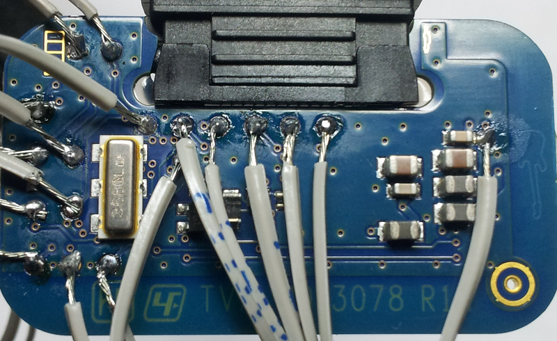
I'm not very happy of my soldering job. Some wires are barely covered by solder, many solder joints have a matt finish. I hope to get some feedback and tips, so I share my bad soldering job in all its high resolution glory here :

I probably should flood this with hot glue to strenghten the connections.
I tripled checked the connections with a continuity tester and everythink was OK and there were no short circuits. I connected the board to my phone and it worked properly. Finally, I wanted to use an seprated power source to test the board.
The board uses a LP2985 power regulator. It takes about 4V from the phone and outputs 2.8V to the board. The datasheet states that the input voltage can go up to 16 volts. Good news, it means that I can be quite careless about the input voltage :-) As a final test, I connected a 5V power source between the Vin and the Gnd pads, and the led blinked !
While my soldering iron was still hot, I soldered the headers of the Trinket. I guess Adafruit's board are pre-tinned and pre-fluxed because it went surprisingly well and I ended with nice and shiny solder joints.
I guess I'm now ready to explore the wonderful world of I²C ;-)
Discussions
Become a Hackaday.io Member
Create an account to leave a comment. Already have an account? Log In.
I re-read your log and was surprised, because It doesn't look like you pre soldered your wires. The wires will definitely conduct the heat better when you solder them to your testpoints, once they are tinned. But using hot glue is nothing to be ashamed of :)
Are you sure? yes | no
I put a little blob of solder on the tip on my soldering iron and tried to apply it to the wires in order to pre-tin them. Most of the time the solder wouldn't stick to the wire :-( In the end, I still managed to get some tinning but it's quite weak. Do you have some tips on how to pre-solder the wires ?
Are you sure? yes | no
Put the iron on your wires first so that they are preheated, then come in with the tin. Thanks to you I just learned that there is a tin type HF34 and a HF32 - last is with flux :) This helps a lot, otherwise get some "Löthonig" - that's flux paste in a tube and quite useful, too.
Are you sure? yes | no