Since I need a way to enter the FM frequency and display it back, I ordered a 7-segment display controlled by I²C. I think it's a good start to play and discover I²C.
Adafruit provides a nice Arduino library for it. After fighting with the Arduino IDE I managed to get some number displayed.
Before going further, allow me a side note here. I'm used to work with JEE applications, a continuous integration server and an IDE that provides me autocompletion and easy code navigation. The Arduino experience is ... well ... quite the opposite. I wonder how anyone can achieve reproducibility with this tangle of custom Arduino IDE, manual library installation and lack of build system. End of side note.
Back to the 7-segment LedBackPack library. I was surprised to see C++ code. I thought that only C was possible on Arduino. I don't know C++ but I know enough of C and Java to survive. The library is well written and easy to use.
However, I don't like how float numbers are displayed on the 7-segment display : the library pads the number with trailing zeros. I want to display FM frequencies and I don't like the way it goes from displaying "99.90" to "100.0". For frequencies under 100Mhz, I just want it to display one decimal digit (" 99.9" for example).
I could patch the LedBackPack library (or override the method, OO FTW !) but I wanted to understand how it worked. I discovered that the library uses the Wire library to emit I²C commands and it's not really complicated :
Wire.beginTransmission(I²C address);
Wire.write(command);
Wire.endTransmission();
and that's all.
After reading the datasheet and poking around, I figured how to control the display myself, without the LedBackPack library. Here is a picture of my findings :
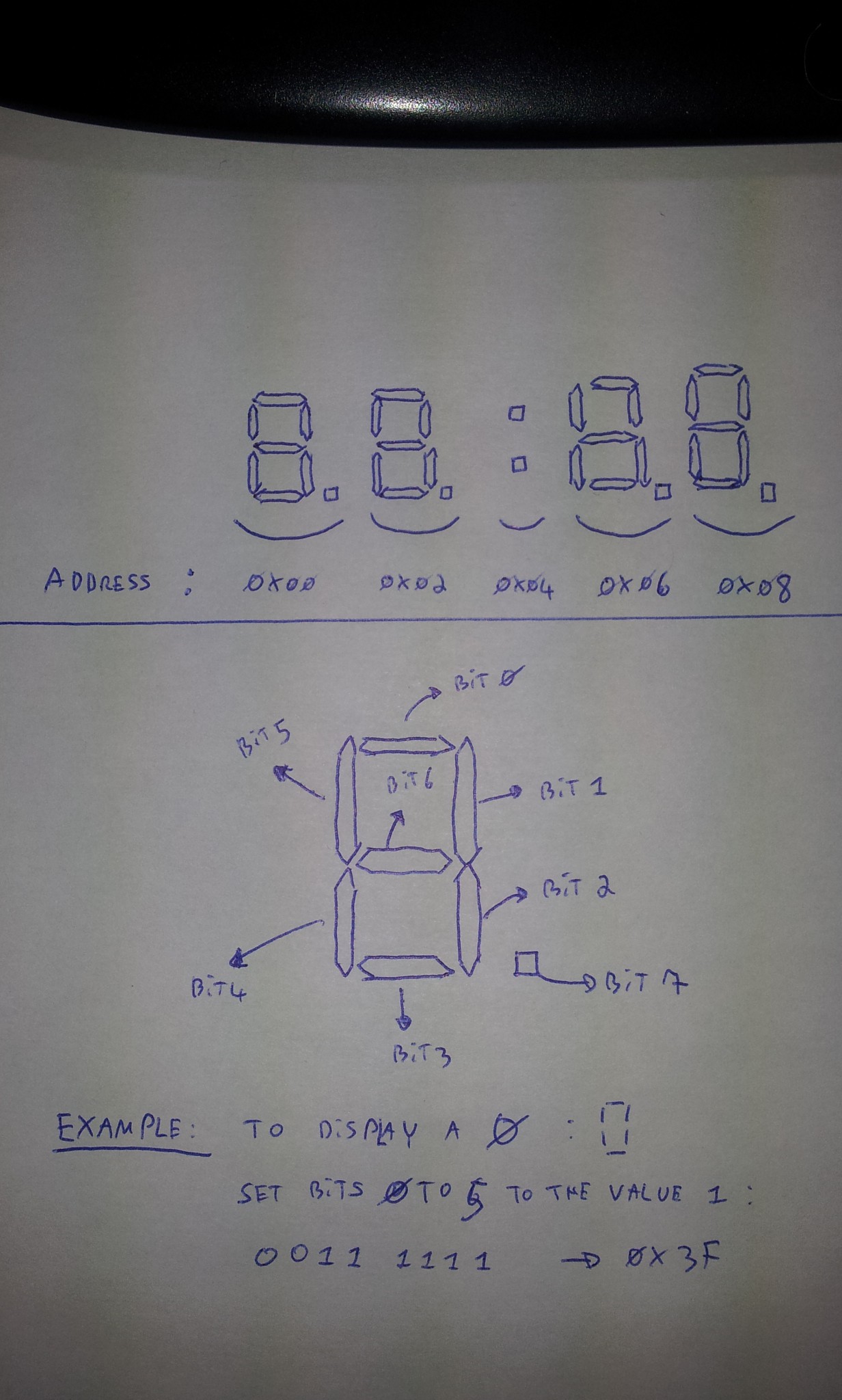
Each 7-segments of the board is located at a specific register. The first 7-segments is at the register location 0x00, the second at 0x02 and so on. To light on or off specific segments of a given 7-segment item, you send a carefully crafted byte at its register address. Each bit of this byte indicates whether the corresponding segment must be on or off.
Let's do an example :
I want to send a command to the display controller. Its I²C addres is 0x70, so I write :
Wire.beginTransmission(0x70);
For this display controller, I want to light some segments of the 7-segments item located after the colon sign. Its register address is 0x06, so I write :
Wire.write(0x06);
For this 7-segments item, I want to display the character 'H'. I thus must lit the segments number 1,2,4,5 and 6. I must create a byte with the corresponding bits set to 1 : 0111 0110 or 0x76. So I write :
Wire.write(0x76);
And finally, I commit the command by writing :
Wire.endTransmission();
Don't forget this last line after each I²C command ! I discovered that two I²C commands inside a single transmission worked fine for me, but with three commands I ended up with a garbled display.
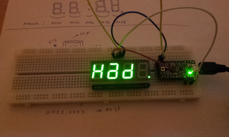
And so, here is my display saying 'Had' in honor to Hack a day :
I'm now more confident to use the Wire library and try to get the FM transmitter working. However, recompiling and uploading a sketch each time I want to test a new I²C command is not fun. So I'm now the proud owner of a Bus Pirate. That should ease things a bit ;)
Discussions
Become a Hackaday.io Member
Create an account to leave a comment. Already have an account? Log In.