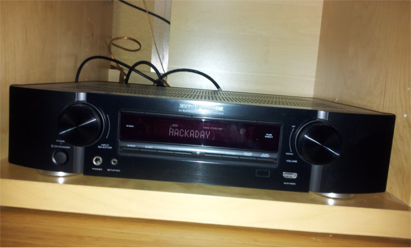
A picture is worth a thousand words. Admire the FM tuner of my AV receiver displaying the name of the famous HACKADAY FM Radio :D
Basically, the RDS system is a way to send digital information to a FM RDS tuner. The RDS specification defines several types of messages called "groups". Each group type can transmit a given set of information. For example, the station name is transmitted in the "OA" type group.
I used the Trinket Pro to send a OA group containing the "HACKADAY" string to the MMR-70.
Well, it's a bit more complicated than that. A OA group can transmit only 2 characters. So I have to send 4 OA groups and keep track of the characters sent. But I cannot sent a OA group directly to the MMR-70. I have to split it in 4 blocks. Oh, and of course, the MMR-70 registers used to send the block varies and depends on the ID of the current block. Oh, and I cannot send the blocks when I want, I have to wait for the RDSINT signal to be LOW.
I will not use the full RDS protocol in this project. All I need is to transmit the station name, and the OA group is enough for that. Here is the code I wrote. It is fully commented, so I hope you can have a better understanding of the RDS group and the MMR-70 by reading it :-)
#include <Wire.h>

// The MMR-70 signals when it's ready to receive the next RDS block by setting
// the RDSINT signal to low.
// Connect this signal to the following pin of the MCU
const uint8_t RDSINT_pin = 8;

// Dont forget to connect the I²C pins of the MCU to the MMR-70
// On the Trinket pro :
// - connect Analog 4/Digital 18 to the SDA point of MMR-70
// - connect Analog 5/Digital 19 to the SCL point of MMR-70


// FM transmitter I²C address
#define NS731_I2C_addr 0x66


// Recommended values for registers initialization
#define NS731_init_data_size 23
const uint8_t NS731_init_data [NS731_init_data_size] = {0x02, 0x81, 0x0A, 0x00,
      0x00, 0x00, 0x00, 0x7E, 0x0E, 0x08, 0xAF, 0x2F, 0x0C, 0xE6, 0x3F, 0x70,
      0xA0, 0xE4, 0x00, 0x42, 0xC0, 0x41, 0xF4};


int RDSINT = 0;     // Status of RDSINT signal from FM transmitter
int RDS_block = 1;  // ID of RDS block inside the current RdS group
int RDS_group = 1;  // ID of the curret RDS group

void setup() {

  pinMode(RDSINT_pin, INPUT);

  // Initialize the wire library
  Wire.begin();

  // Send a reset command to the FM transmitter
  Wire.beginTransmission(NS731_I2C_addr);
  Wire.write((uint8_t)0x7f);
  Wire.write((uint8_t)0xa0);
  Wire.endTransmission();

  // Initialize the registers of the FM transmitter with the recommanded values
  for (uint8_t i; i<NS731_init_data_size; i++) {
    Wire.beginTransmission(NS731_I2C_addr);
    Wire.write(i);
    Wire.write(NS731_init_data[i]);
    Wire.endTransmission();
  }

  delay(700);

  //Set PE to ON
  Wire.beginTransmission(NS731_I2C_addr);
  Wire.write((uint8_t)0x00);
  Wire.write((uint8_t)0x03);
  Wire.endTransmission();

  delay(150);

  //Set ALC to ON
  Wire.beginTransmission(NS731_I2C_addr);
  Wire.write((uint8_t)0x0d);
  Wire.write((uint8_t)0xe7);
  Wire.endTransmission();

  // Set mute to ON
  Wire.beginTransmission(NS731_I2C_addr);
  Wire.write((uint8_t)0x02);
  Wire.write((uint8_t)0x0b);
  Wire.endTransmission();

  // Set frequency
  Wire.beginTransmission(NS731_I2C_addr);
  Wire.write((uint8_t)0x0a);
  Wire.write((uint8_t)0xea);    // 0XEA 0X2A is 90.0 Mhz
  Wire.write((uint8_t)0x2a);    // Change those values to change the frequency
  Wire.endTransmission();

  // Set P2 to recommended value
  Wire.beginTransmission(NS731_I2C_addr);
  Wire.write((uint8_t)0x07);
  Wire.write((uint8_t)0x7e);
  Wire.write((uint8_t)0x0e);
  Wire.endTransmission();

  // Wait for CEX search time
  delay(900);


  // Set MAA according to CEX value
  Wire.beginTransmission(NS731_I2C_addr);
  Wire.write((uint8_t)0x15);
  Wire.write((uint8_t)0x21);   // You should first read the CEX value and set
  Wire.endTransmission();      // MAA accordingly. Here the 0x21 value is good
                               // for the default 90.0 Mhz transmission
                               // frequency. You should change it if you use
                               // another frequency (see the datasheet).

  // Set mute to OFF
  Wire.beginTransmission(NS731_I2C_addr);
  Wire.write((uint8_t)0x02);
  Wire.write((uint8_t)0x0a);
  Wire.endTransmission();

  // Activate RDS
  Wire.beginTransmission(NS731_I2C_addr);
  Wire.write((uint8_t)0x10);
  Wire.write((uint8_t)0xe0);
  Wire.endTransmission();

  delay(15);

}


// In this loop we continuously send the RDS Station Name.
//
// The Station Name is contained inside a "RDS Group" of type "OA". However, a
// single OA group is not enough to contain the full 8 characters of the station
// name. So we must sent it in four times, each of the 4 RDS groups containing
// 2 characters of the station name.
//
// But we cannot send all the 4 RDS OA groups at once. We cannot even send one
// full OA group at once, the RDS transmitter does not support it. Instead, a
// RDS group is divided in 4 RDS blocks. Each block is sent one at a time.
//
// We cannot send a RDS block when we want it. We must wait for the FM
// transmitter. When the RDSINT signal is low, it means that its ready to
// receive the next block.
void loop() {

  // Read the RDSINT status
  RDSINT = digitalRead(RDSINT_pin);

  if (RDSINT == LOW) {  // The FM transmitter is ready to receive the next
                        // RDS block
    Wire.beginTransmission(NS731_I2C_addr);
    switch(RDS_block) {

      // First block of a OA group. Contains the PI, i.e. the station ID
      case 1:
        Wire.write((uint8_t)0x03);  // First group must be sent to 0X03 register
        Wire.write((uint8_t)0xe0);  // but others must be sent to 0X05.
        Wire.write((uint8_t)0x00);
        break;

      // Second block of a OA group. Contains the type of group (OA),
      // the PTY (program type), a Music/Speech flag...
      // The DI information and the Station name need to be sent in multiple
      // OA groups. So this block also contains the address of the current
      // group (1, 2, 3 or 4).
      // We keep track of the groups sent through the RDS_group variable and
      // transmit the correct DI and address accordingly.

      case 2:
        Wire.write((uint8_t)0x05);
        Wire.write((uint8_t)0x01);
        switch(RDS_group) {
          case 1:
            Wire.write((uint8_t)0x24);
            break;
          case 2:
            Wire.write((uint8_t)0x21);
            break;
          case 3:
            Wire.write((uint8_t)0x22);
            break;
          case 4:
            Wire.write((uint8_t)0x27);
            break;
        }
        break;

      // Third block of a OA group. Contains the alternative frequency.
      case 3:
        Wire.write((uint8_t)0x05);
        Wire.write((uint8_t)0xe0);
        Wire.write((uint8_t)0xcd);
        break;

      // Fourth block of a OA group. Contains the radio station name (8 chars).
      // Each OA group can be used to send 2 characters at a time. We thus need
      // to send 4 OA groups in total to transmit the station name.
      // We keep track of the groups sent through the RDS_group variable and
      // transmit the correct set of two characters accordingly.
      case 4:
        Wire.write((uint8_t)0x05);
        switch(RDS_group) {
          case 1:
            Wire.write((uint8_t)0x48); // Letter H
            Wire.write((uint8_t)0x41); // Letter A
            break;
          case 2:
            Wire.write((uint8_t)0x43); // Letter C
            Wire.write((uint8_t)0x4b); // Letter K
            break;
          case 3:
            Wire.write((uint8_t)0x41); // Letter A
            Wire.write((uint8_t)0x44); // Letter D
            break;
          case 4:
            Wire.write((uint8_t)0x41); // Letter A
            Wire.write((uint8_t)0x59); // Letter Y
            break;
        }
    }
    Wire.endTransmission();

    // Keep track of RDS block sent inside a RDS group
    RDS_block++;
    if (RDS_block > 4) {
      RDS_block = 1;
      // Keep track of RDS groups sent
      RDS_group++;
      if (RDS_group > 4) RDS_group = 1;
    }
  }
}
Discussions
Become a Hackaday.io Member
Create an account to leave a comment. Already have an account? Log In.
Thank you for the code! I cross checked the bytes with the data sheet and found out that the third byte, when changed to 0xCA instead of 0x0A should increase the transmitter power. It works on the atmega32 by the way!
Are you sure? yes | no
You're welcome. I'm glad you found my (ugly) code useful !
I stayed on the safe side and reused the exact init data sent by the GSM, but I guess a little more transmitter power will not hurt ;-)
Are you sure? yes | no
It's not that ugly, really - I liked the for loop for the int data! You could have put that all in to functions, but it actually helps comparing it to the datasheet. And the documentation/comments help as well :)
I might turn it back to the low side as well, I was just eager to test it.
Are you sure? yes | no