 Alex Lovegrove
PLYWOOD EXCAVATOR - THE BUILD...
- - - Massive thanks to Steve Knight the ultimate tinkerer for letting me use his mind and his workshop - - -
I have followed projects showcased here on Hackaday for what now seems like forever. It never ceases to amaze me the ingenuity of people featured so Its my absolute pleasure to post this project here... Thanks Hackaday!
Not entirely sure where to start so apologies if this project reads badly, just look at the pretty pictures and work out how I did it. I also really struggled to name all the parts or be consistent with naming of parts. I was just making it up as I went along!

Scale - At first i needed to find a suitable template to design the excavator shape and get the proportions just right to fit a 5 year old. After some googlefu I found the image below and set about scaling it to fit and tracing lines over the main elements to get a feel for the basic shape.

Safety First - obviously a small child and pinching parts is a possible recipe for disaster so I took along time to consider safety.
The most complicated part of the machine is the caterpillar tracks and It took me quite a while to figure out how this was going to work. I was conscious that a small child's fingers could get stuck in the gears and the track links, however I wanted an authentic caterpillar track look, so compromises had to be made.
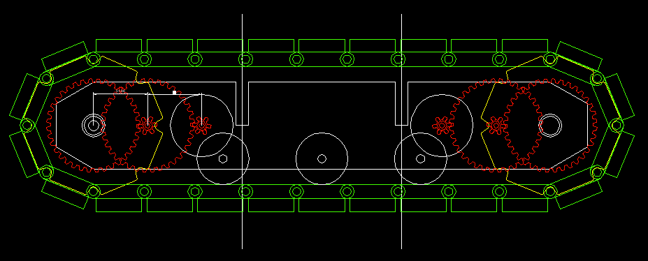
Caterpillar Tracks - Initially I wanted to use plywood for everything possible even the chain links for the caterpillar track. Getting the gearing to mesh with tracks was interesting and I found gear generator program and played around until the correct number or track paddles and links where fully realised. The images below show this development.
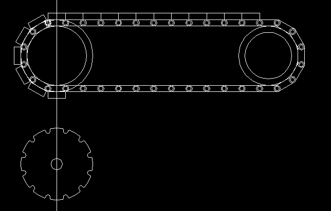
The drive gear and chain above had way to many links to be easily fabricated so I decided to reduce the number.
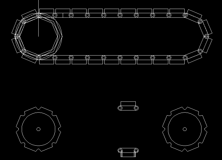
As can be seen the reduction in track links simplifies the entire design.
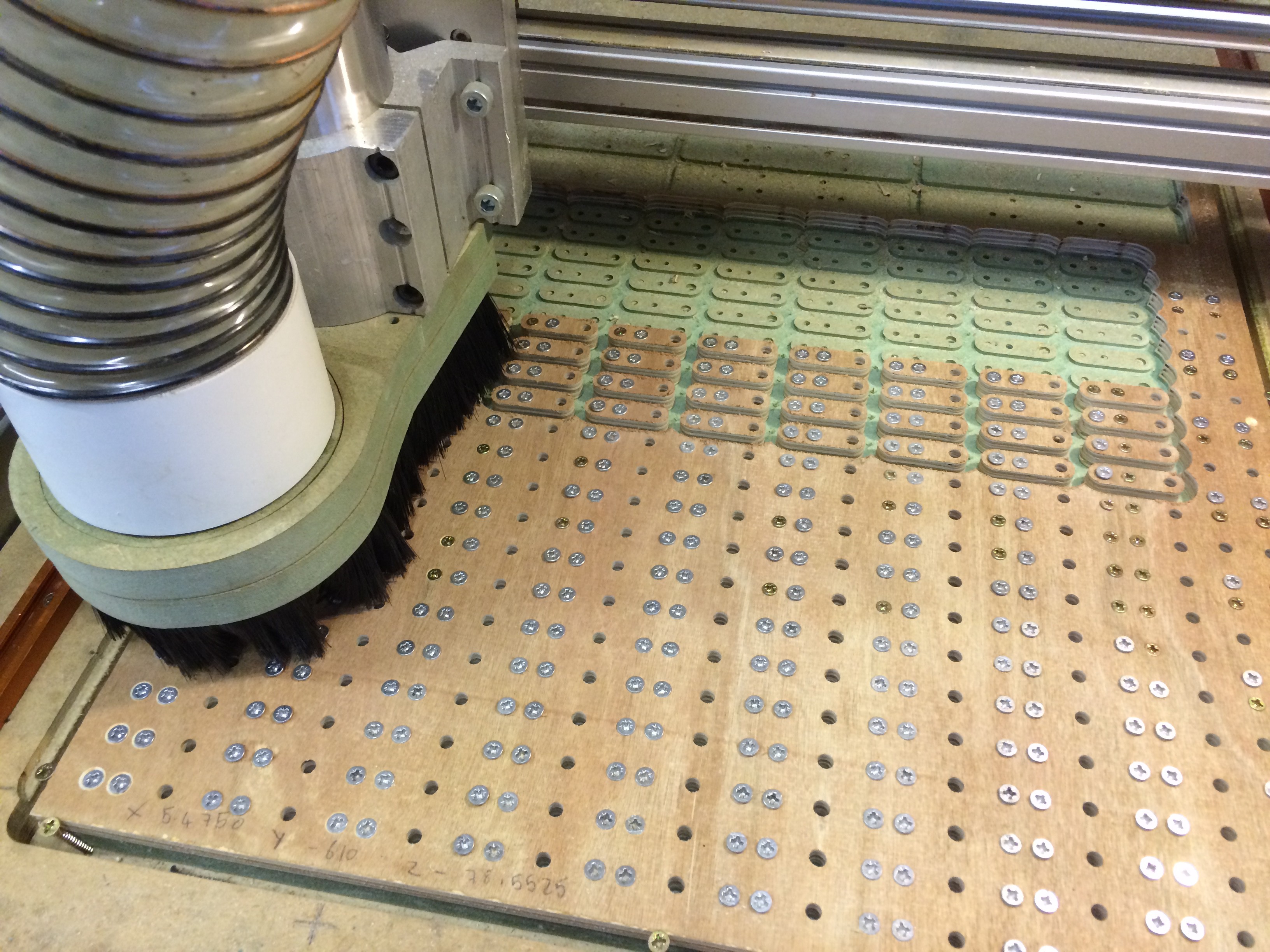
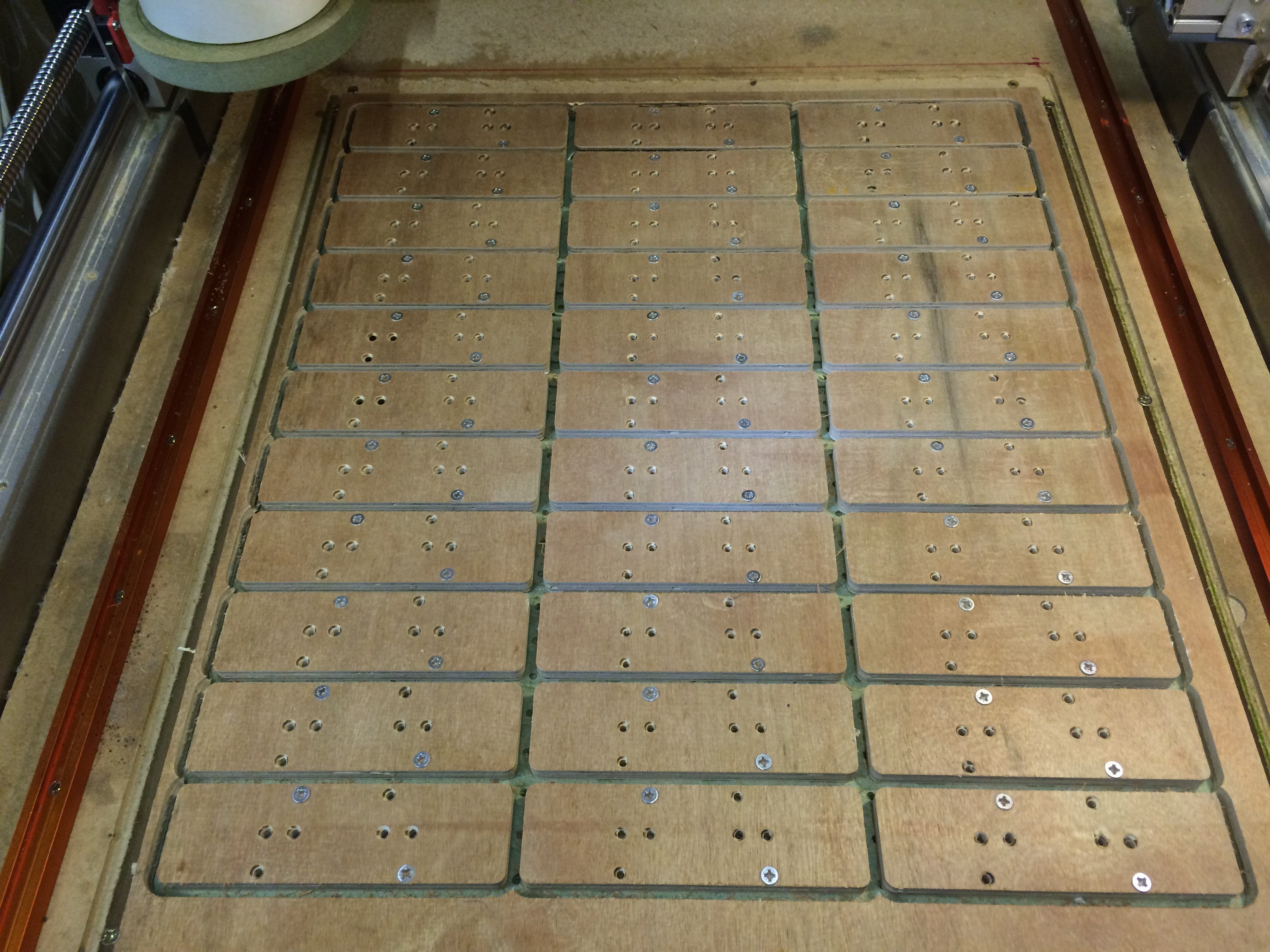
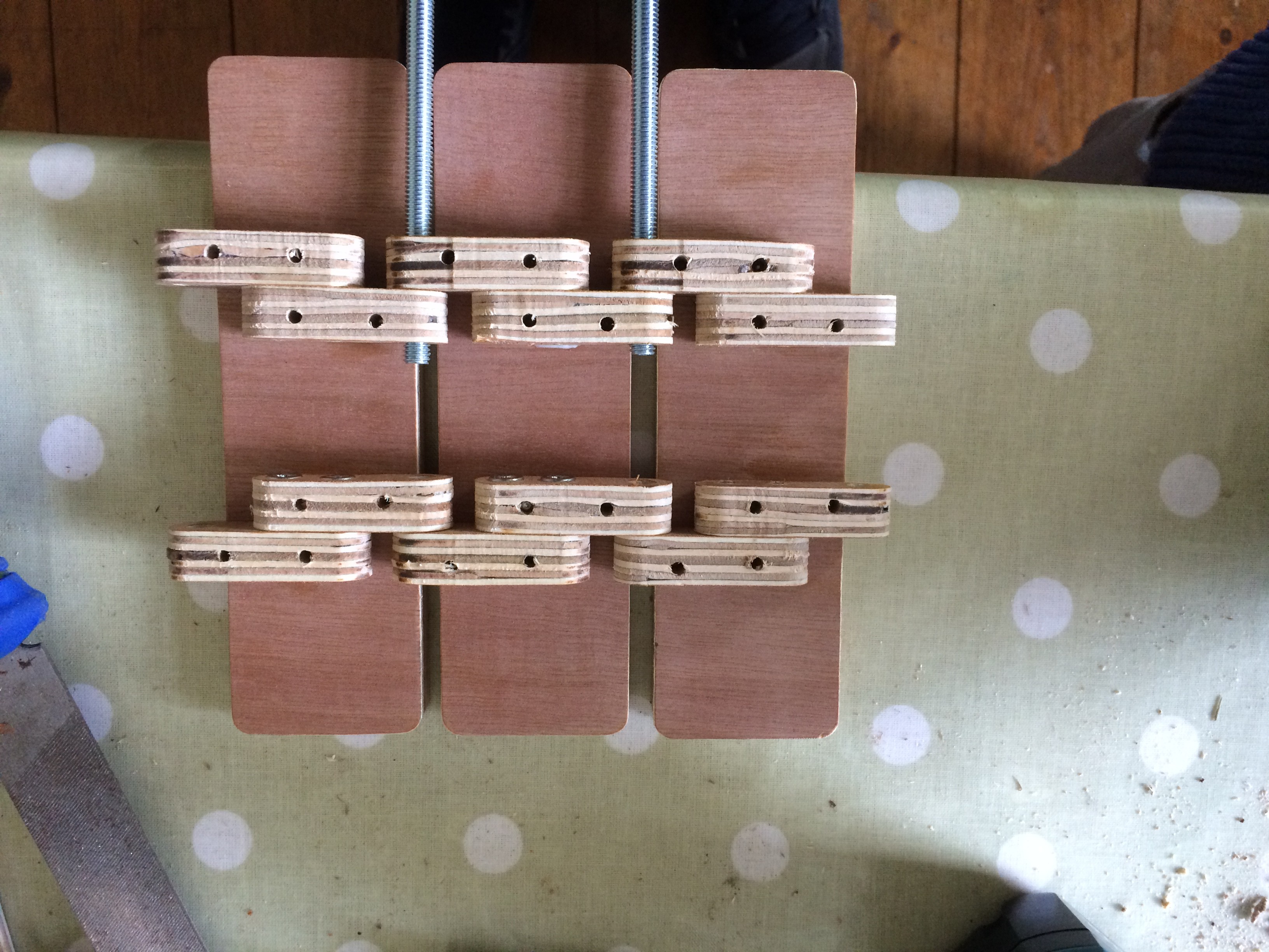
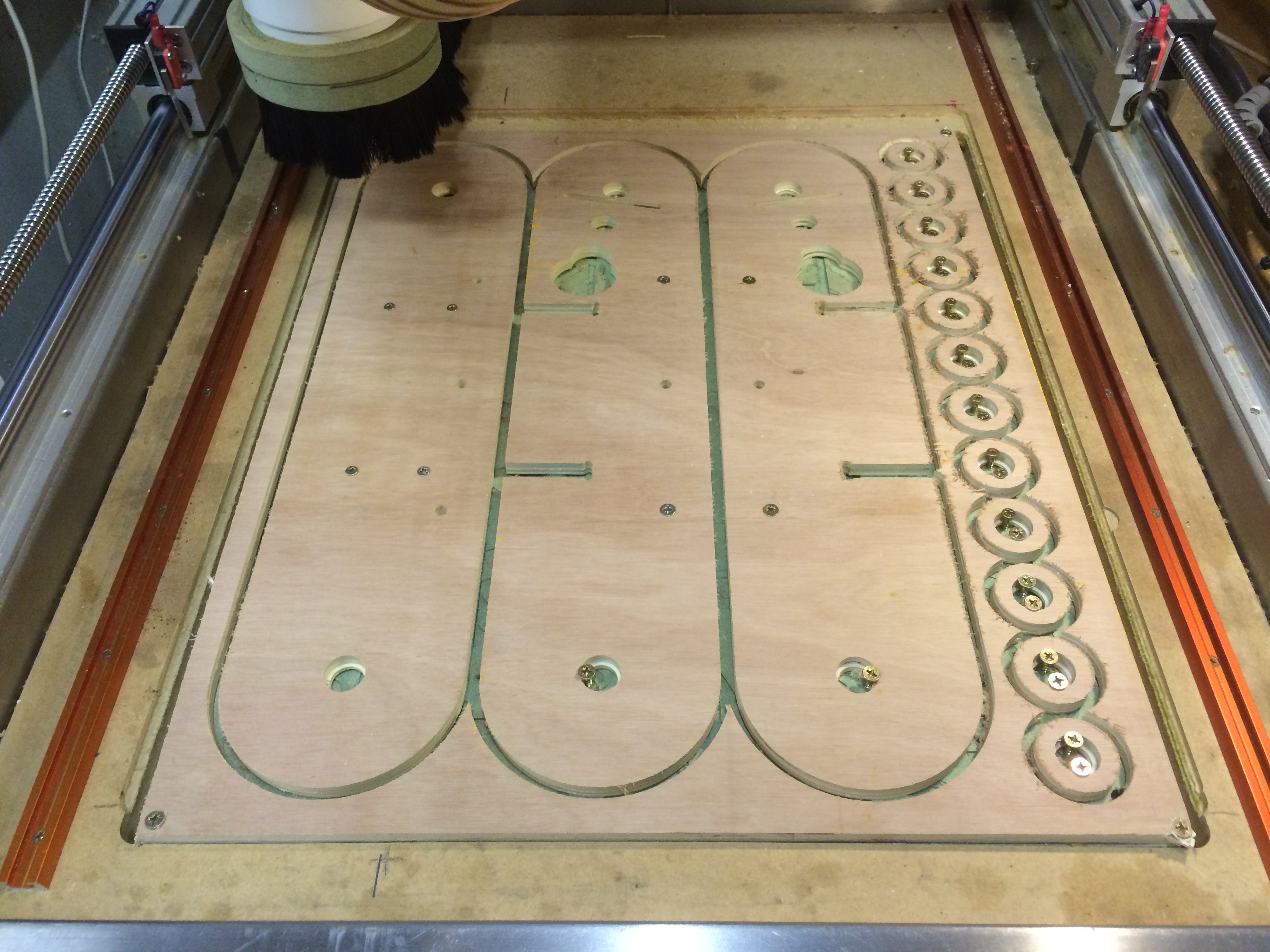
I then set about trying to make a very slender chain from plywood links. The images below show the machining of the links. I don't have a vacuum bed so each link had to be predrilled then screwed down before machining the profiles.
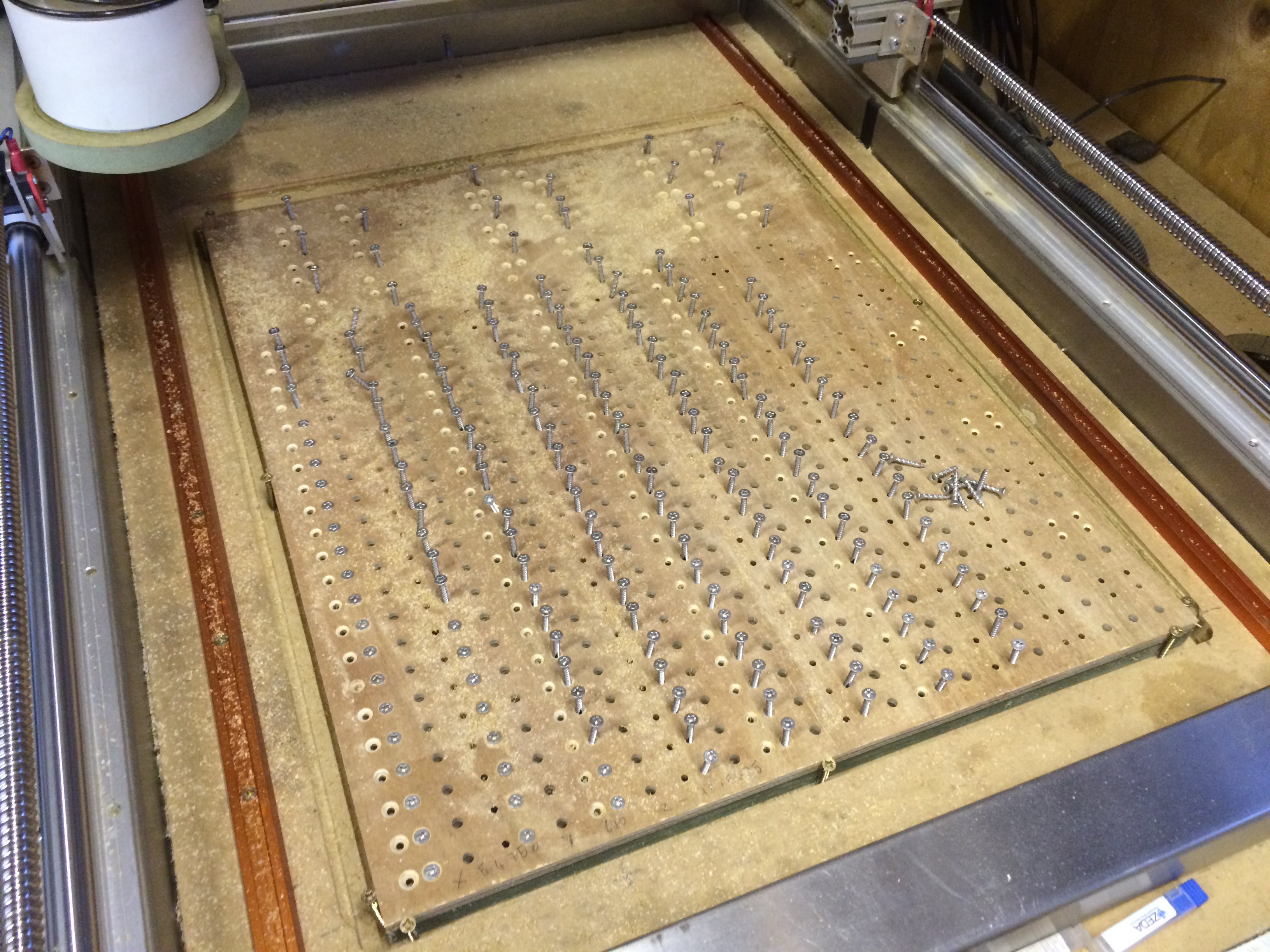
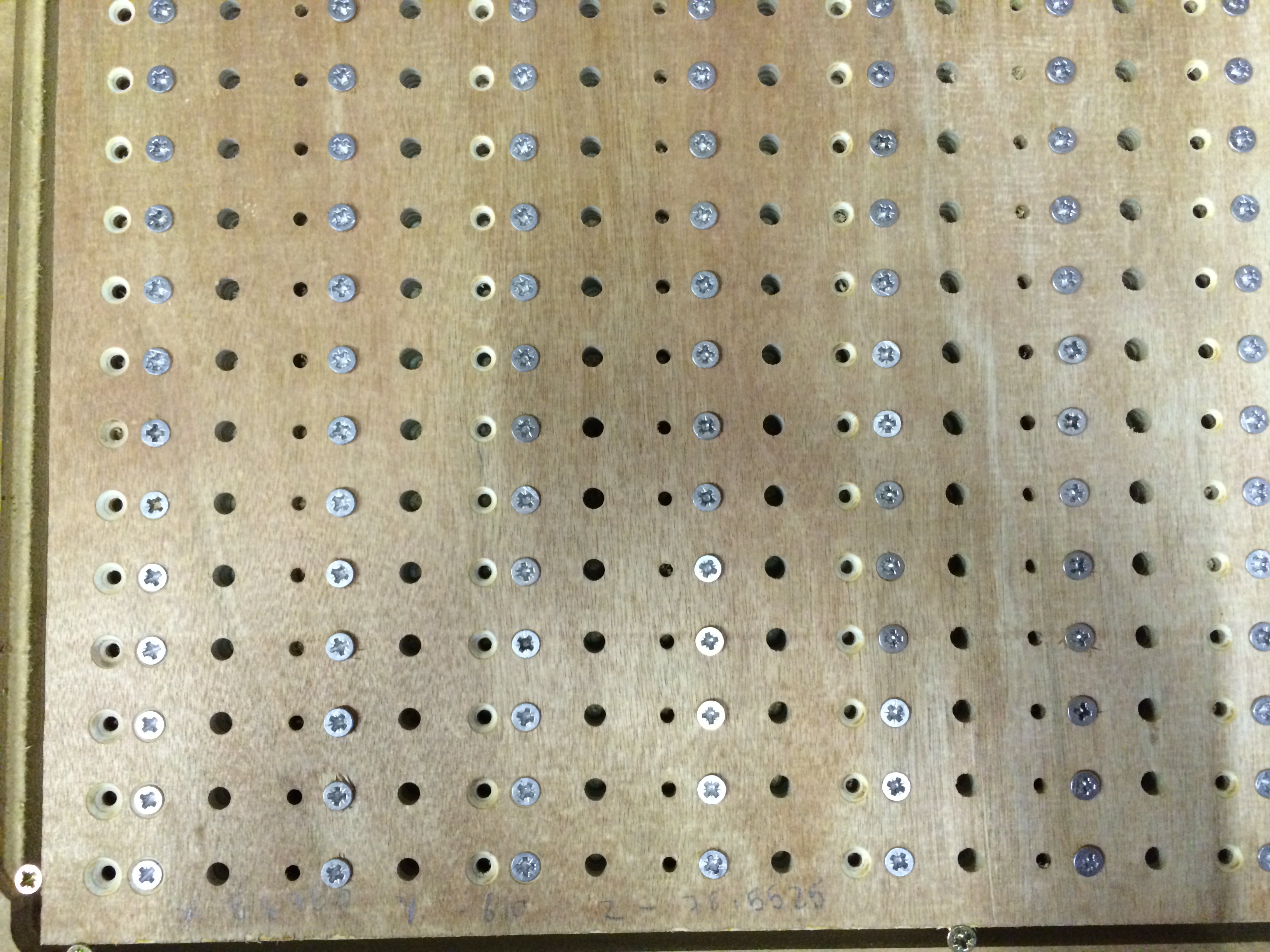
6mm holes for the pins, 3mm for the screws countersunk naturally!
Final profile cut.
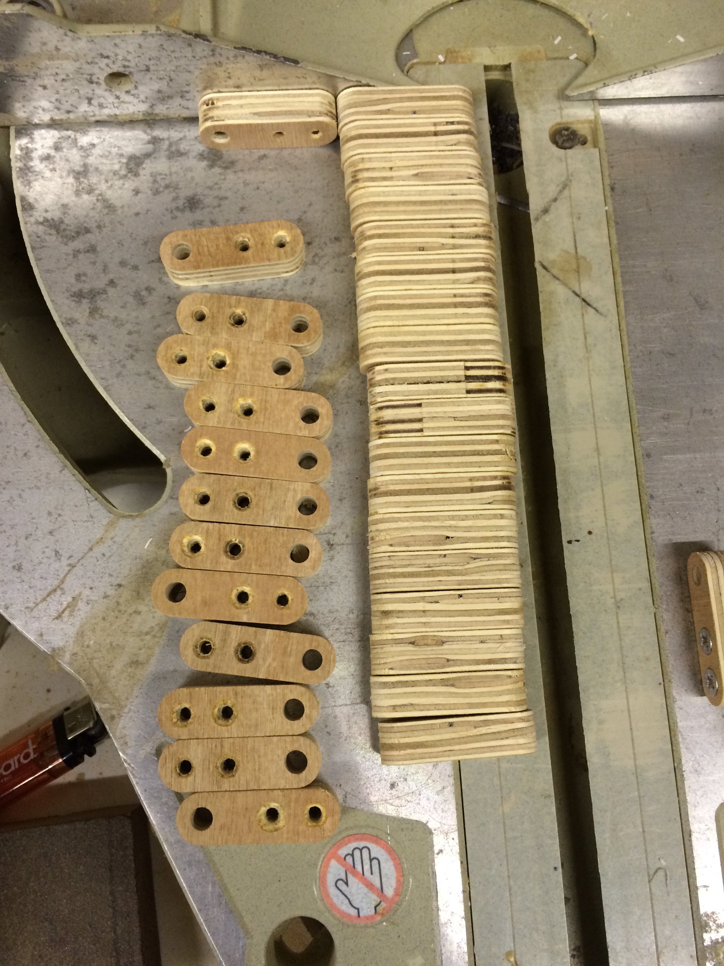
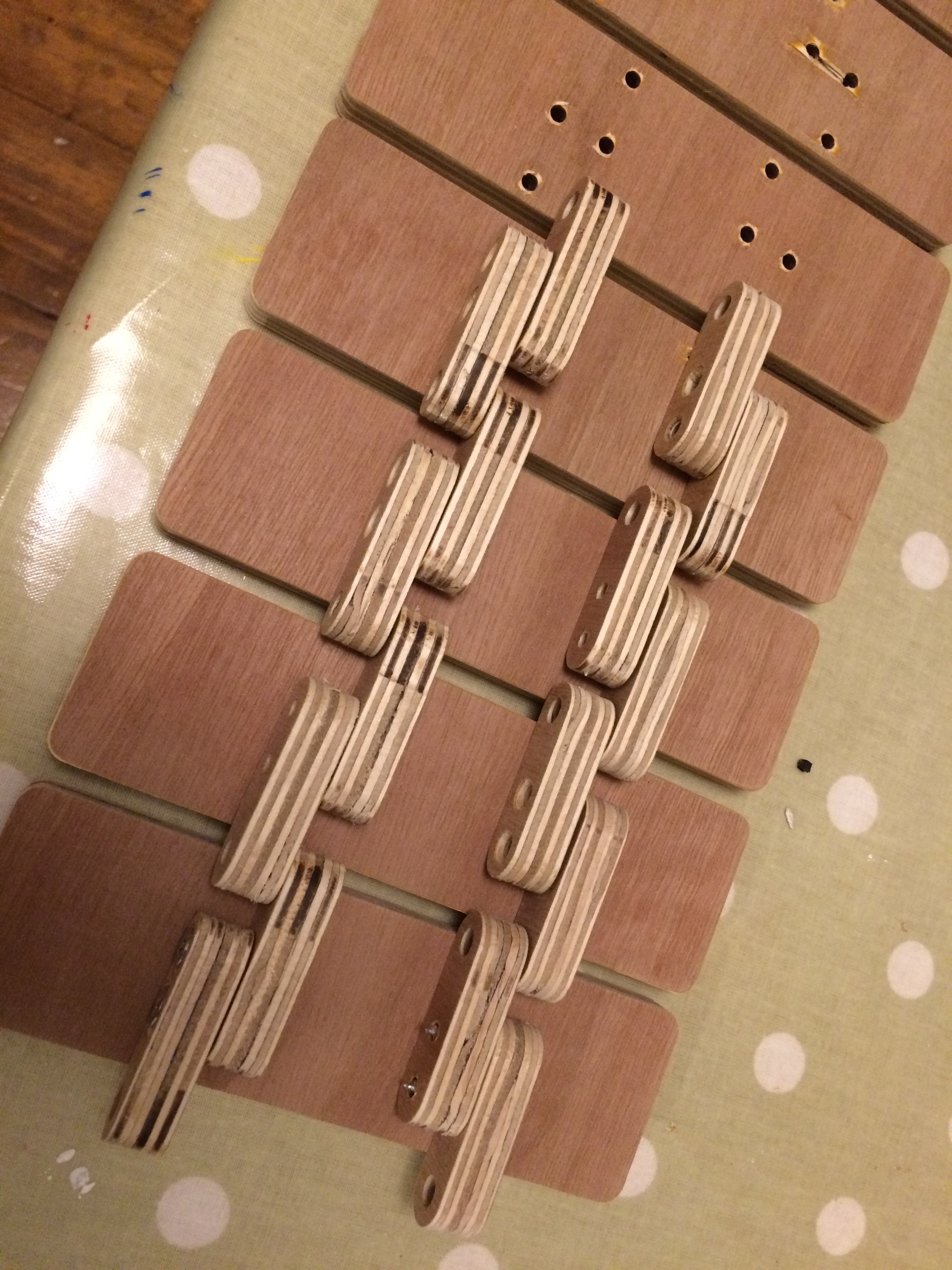
Final links ready to be stuck together. Glued and screwed with stainless screws
Machining out the Track Paddles / Plates? Not sure what they are called? Answers on a postcard please!
6mm coach bolts to pivot the links and engage with the drive wheel. The heads where later cut off and replaced with nylock nuts.
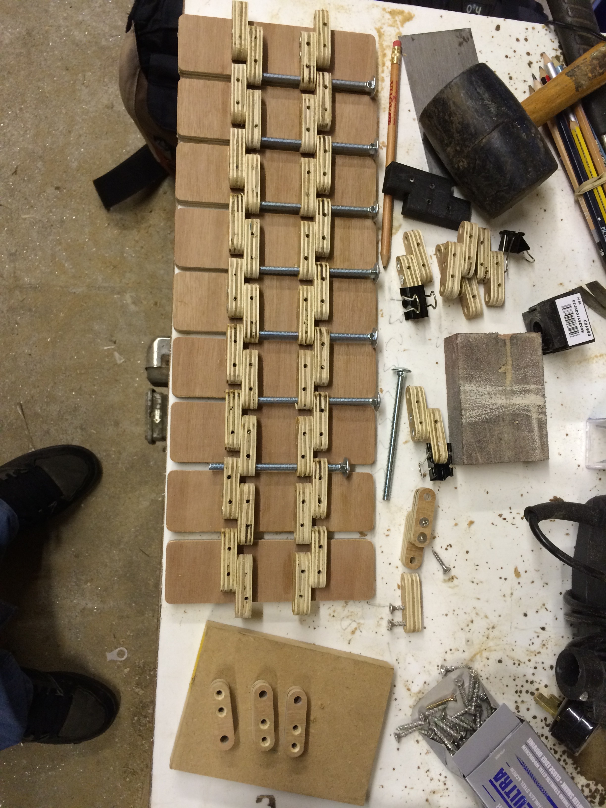
The picture above shows the very first iteration which worked well for a bit but the links were very heavy with the many many screws helping to hold them together. Also the quality of the ply used was not good. This resulted in the links breaking under strain. More on that later...
The picture below is of the drill jig for the chain links to mount the track paddles. I soon discovered that all the screws where increasing the weight and each Paddle only really needed 2 screws and PVA glue.
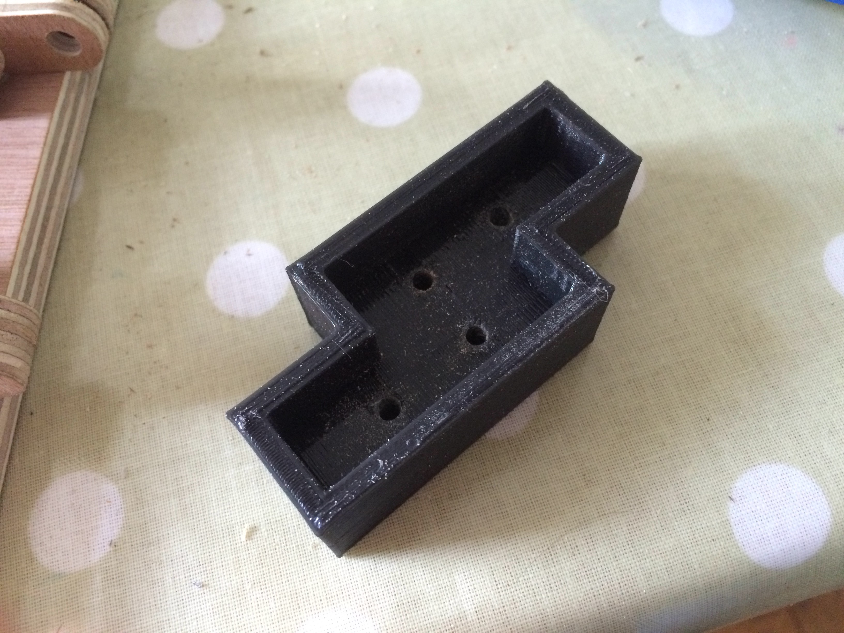
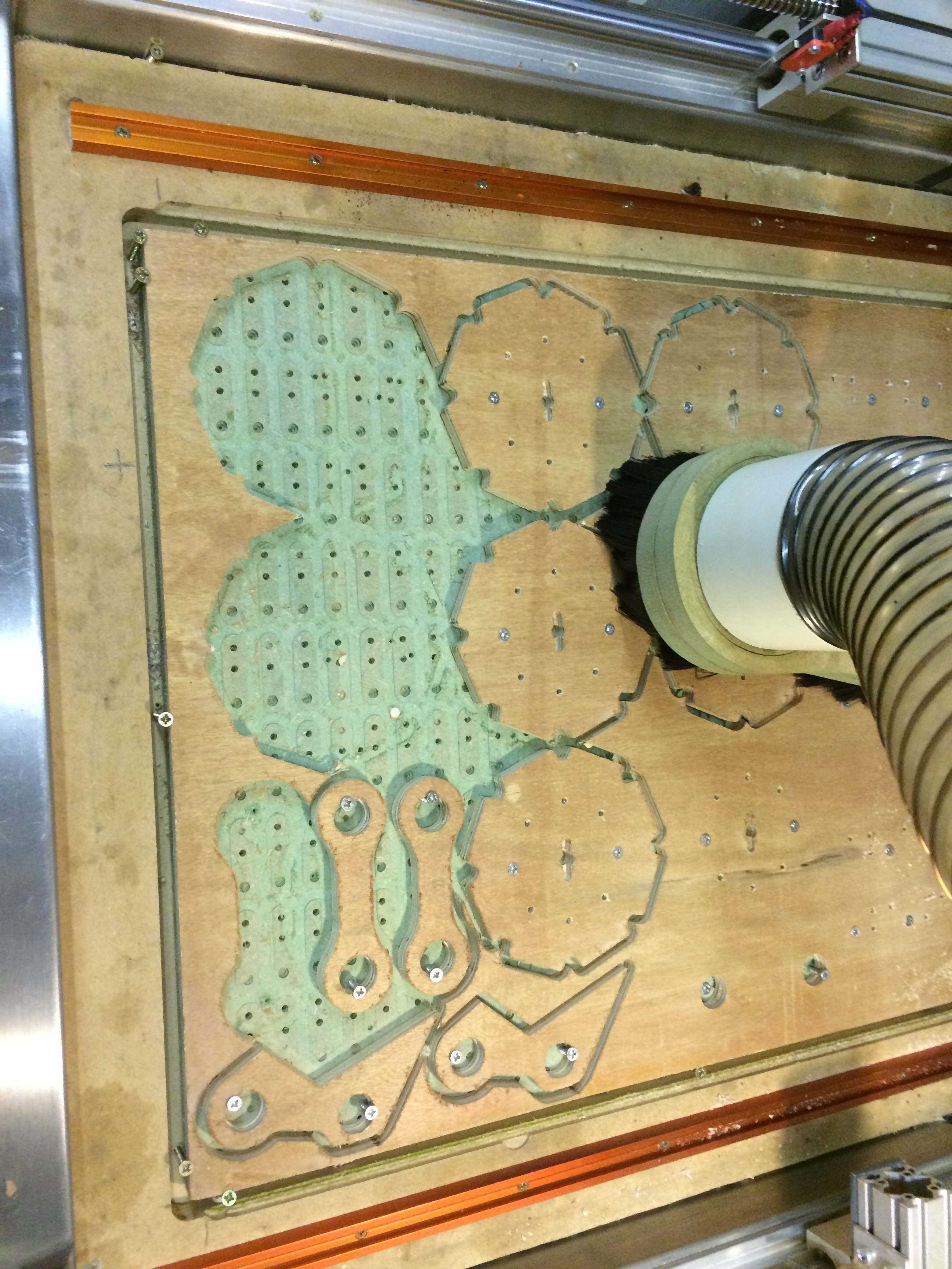
Image above show machining of the prototype drive wheels.
Drive System - Initially I had planned on using a pair of cordless drills to drive the tracks, so I set about devising a gear train for this purpose. With 3D printed gears and galvanised threaded studding.
Note the introduction of Idler Wheels.
One concept track with side guard to prevent fingers from getting into the drive train.
Testing.....

3D Model of the pinion coming straight of the drill.
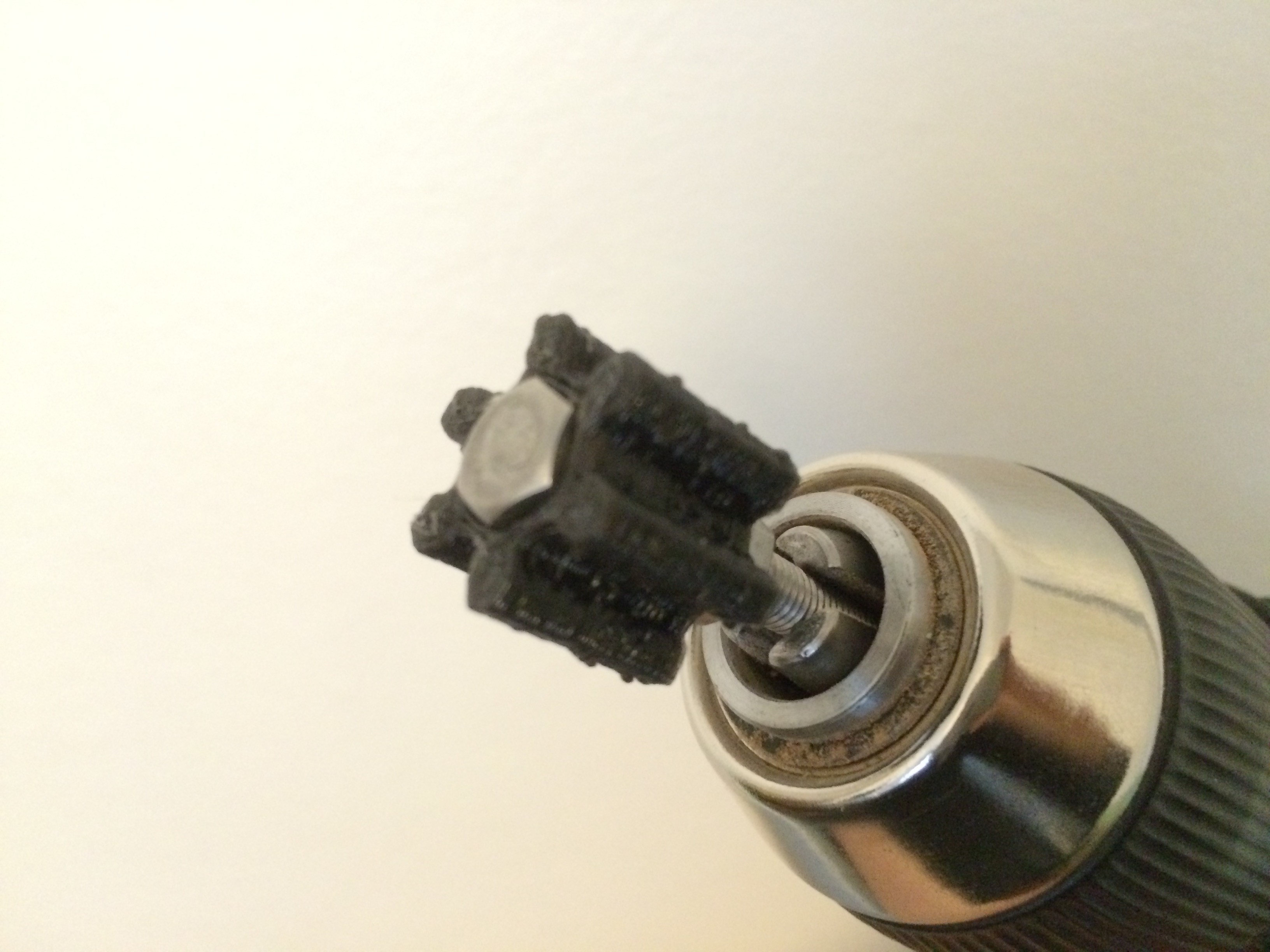
Blobby print!!! PLA CTC printer, issues with thermocouple on hot end. It does the job.....
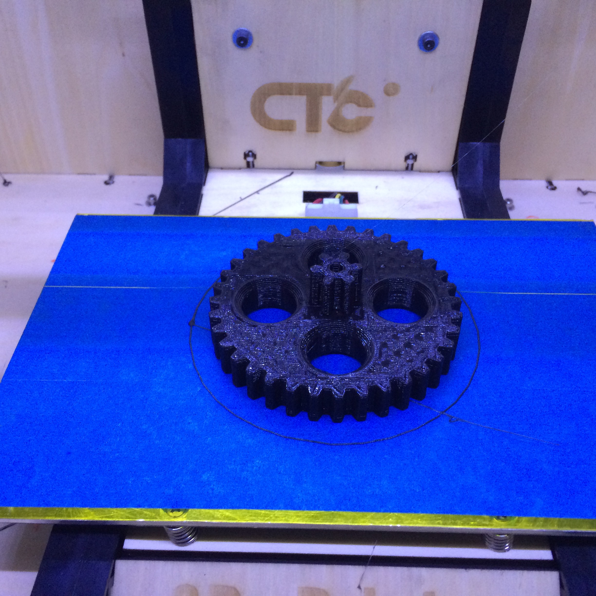
Printing drive gear

Very rough assembly of the tracks and working out the centre frame

Bearing block and drive assembly test....
It soon became clear that the drive was too complicated, not strong enough as the pinion kept cracking. Also the converting two drives and adapting the triggers and extending the battery packs was both expensive and awkward.
I needed to find a better alternative.
I was looking at Power Wheels and discovered that you can buy the gear boxes really cheaply. So I opted to use these instead. Loads of torque, cheap and 12V. Perfect...
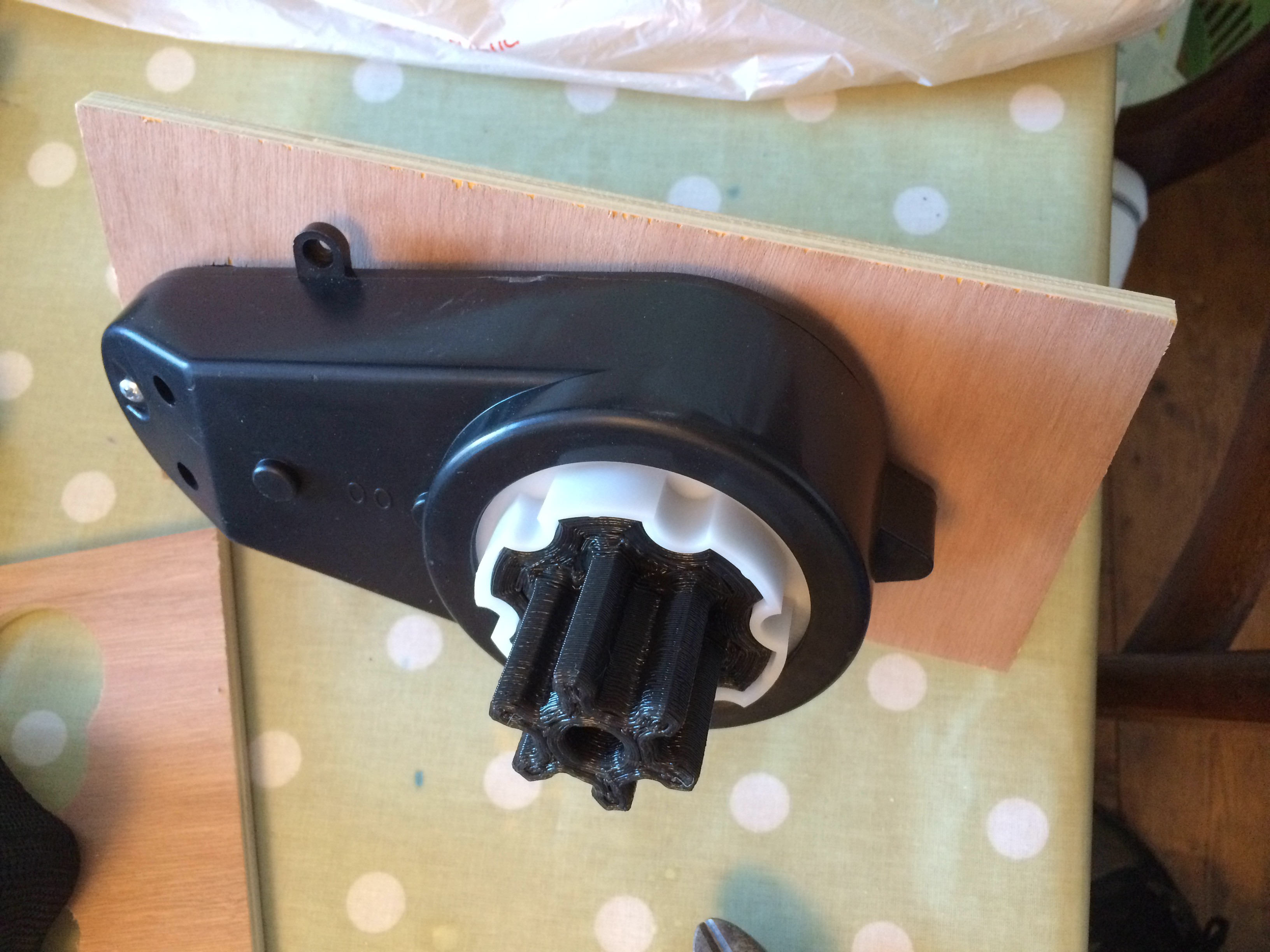
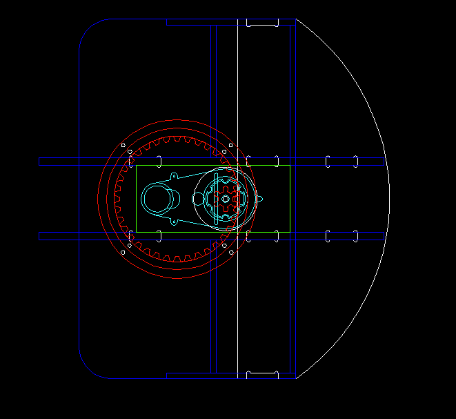
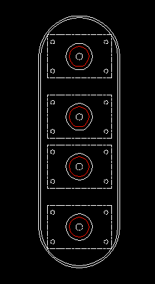
The above image is of the slew gear also 3D printed in PLA. Just to show you what the Power Wheels gear box looks like. This one part solved three problems in one go!
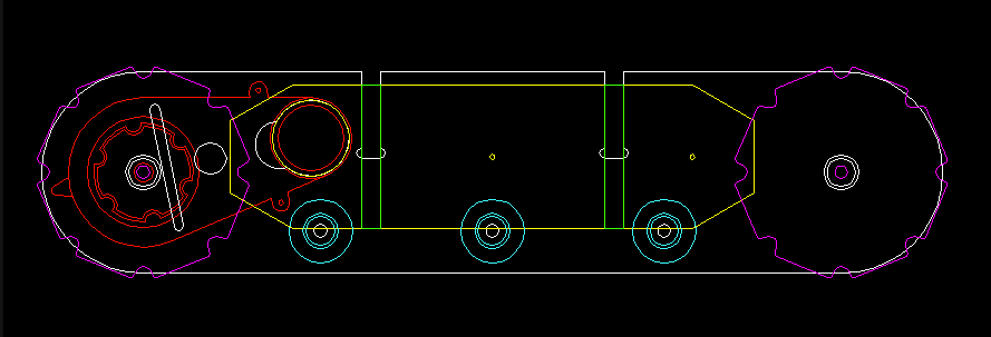
The Red lines denote the gearbox
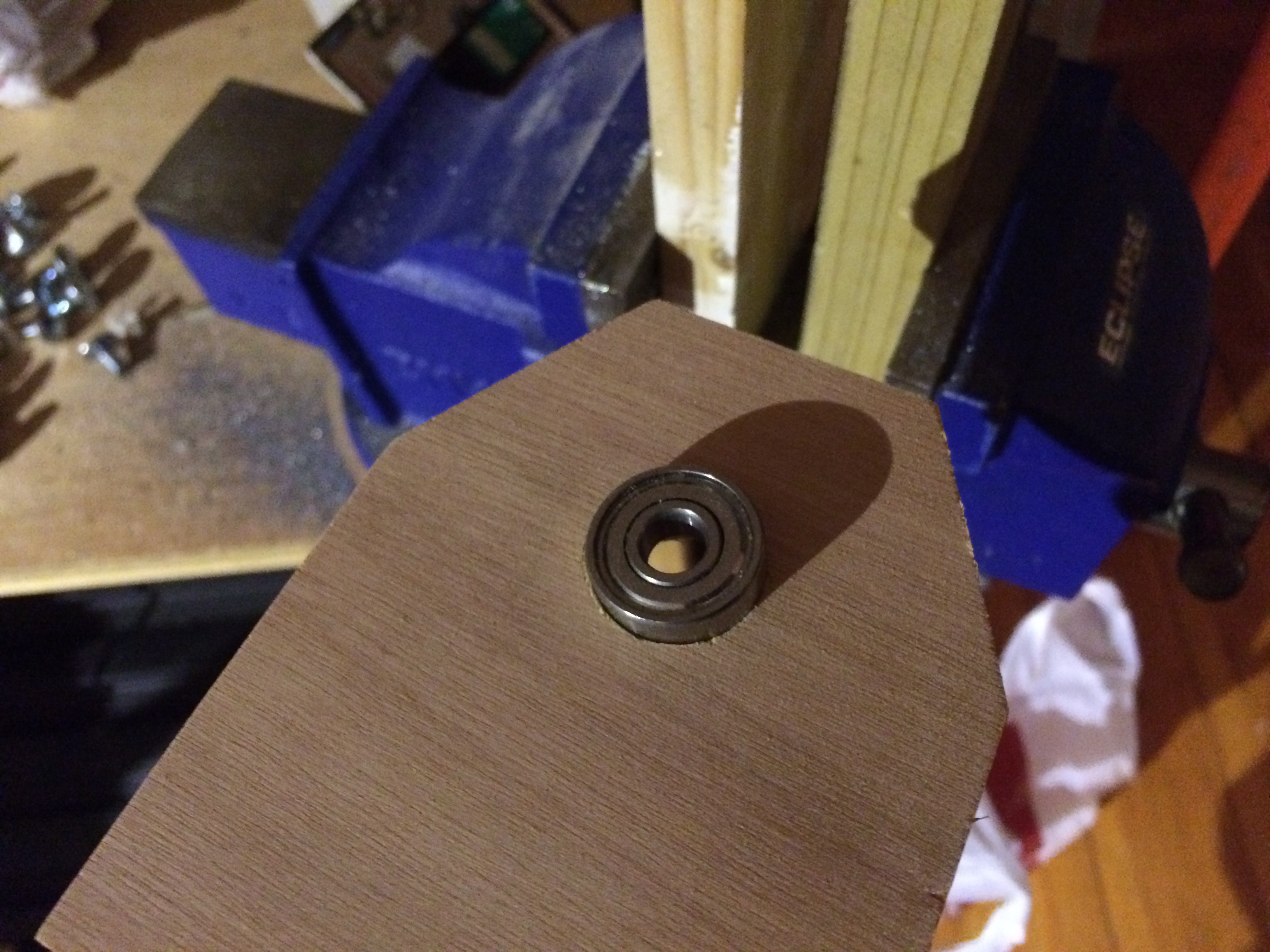
Press fitting bearings into ply, satisfaction guaranteed!
Above photo is of the inside plate of the RHS track the slot is for the Power Wheels gearbox fin and the hole is for the gear box protrusion.
After a lot of testing and fiddling about I had finally managed to make a caterpillar track that functioned fairly well.
Arcade Stick Two Relays and a PW Gear Box from Alex Lovegrove on Vimeo.
Jumping ahead slightly I wanted to show you how the control for the tracks will work. The video above shows a 2200mah Lipo Battery connected to two relays, Arcade Joystick and Power Wheels gear box. The relays work together to switch the polarity of the battery to run the motor forwards and backwards. This is quick and dirty but it works really well. Originally I wanted to have proportional control so the tracks would accelerate but In the end I opted for a simpler solution to keep the cost down.
Plywood Caterpillar Tracks First Trundle from Alex Lovegrove on Vimeo.
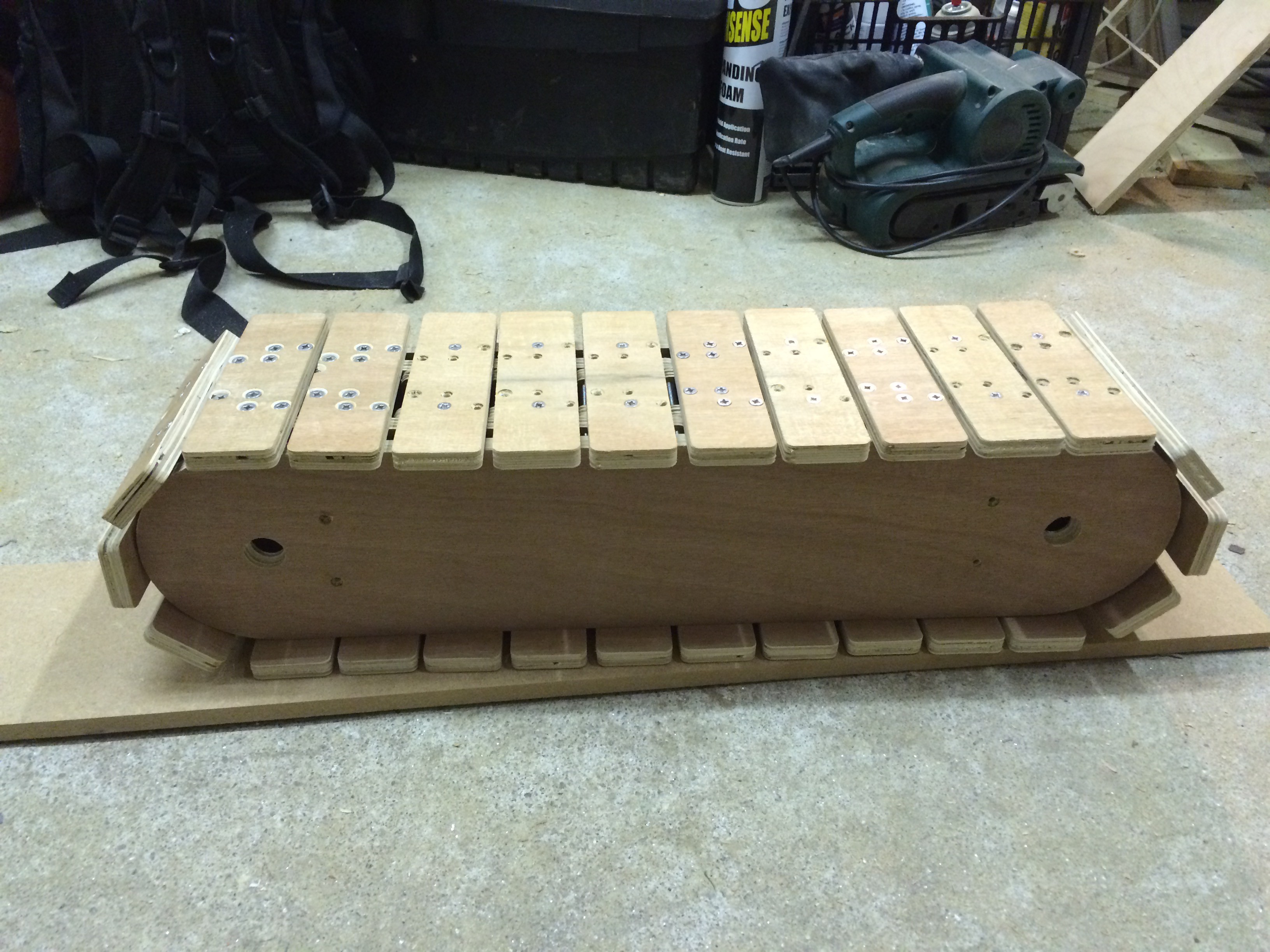
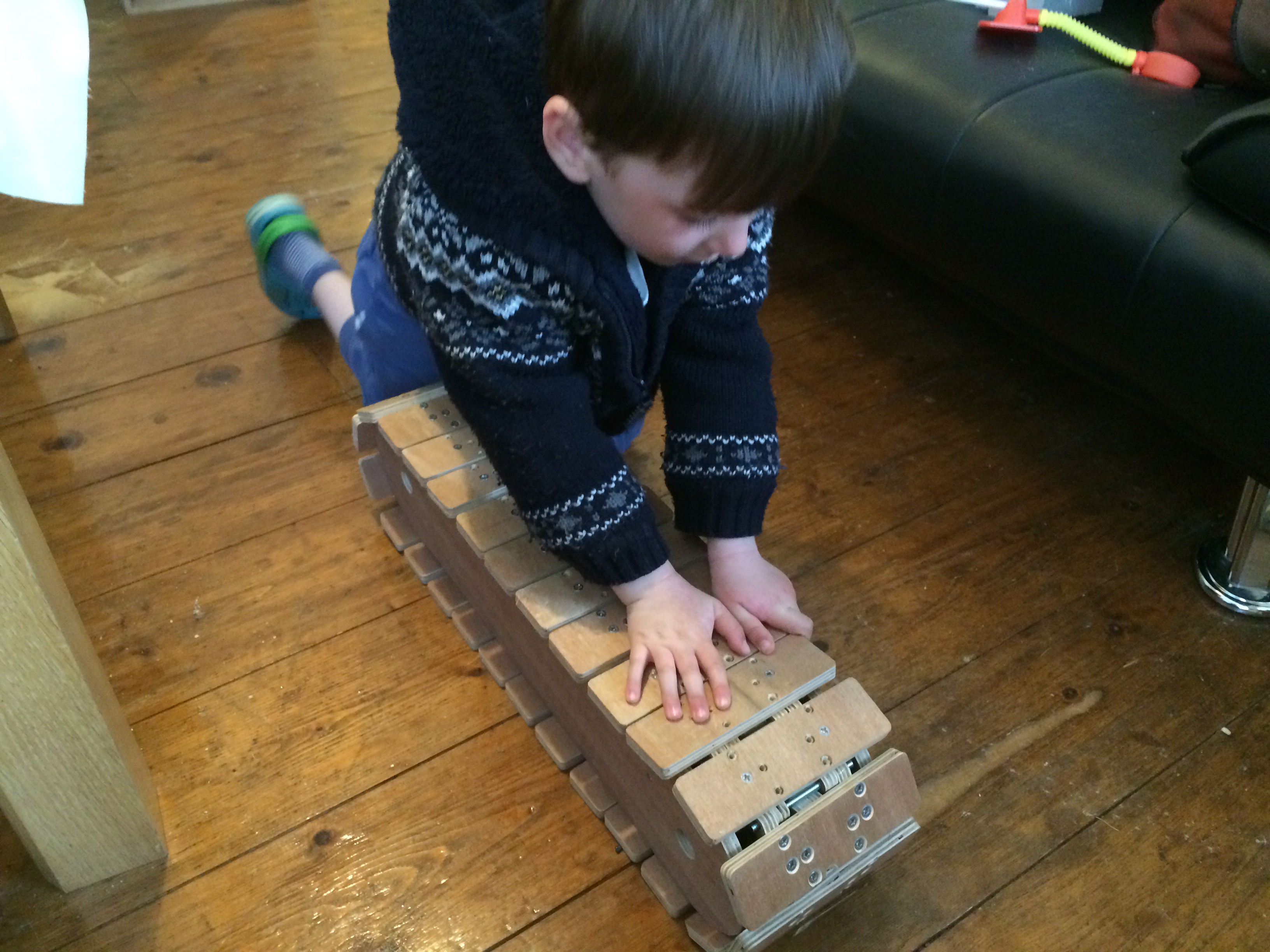
A quick check for scale with the prototype tracks... Like a Glove! Note the Ply Bicycle in the background.... Another project I need to share!

Behold the Lazy Susan. The spec sheet for this one states maximum load of 100kgs! Not sure I believe the specs... This is the pivot on which the top of the excavator rotates...

Checking the fit of all the parts.
At this point I had redesigned the caterpillar tracks and had tested the prototype set to destruction. The original drive gear had flat teeth that would catch the edge of the track chain and throw the chain off. This snapped links and generally caused bad things to happen. Also because the ply I used was very cheap the links were not really strong enough to handle the tension.
I decided to 3D print the track links as this saved weight and they were much stronger. I also beveled the drive gears front and rear, this prevents the gear catching the side of the track chain. It seems to work flawlessly.
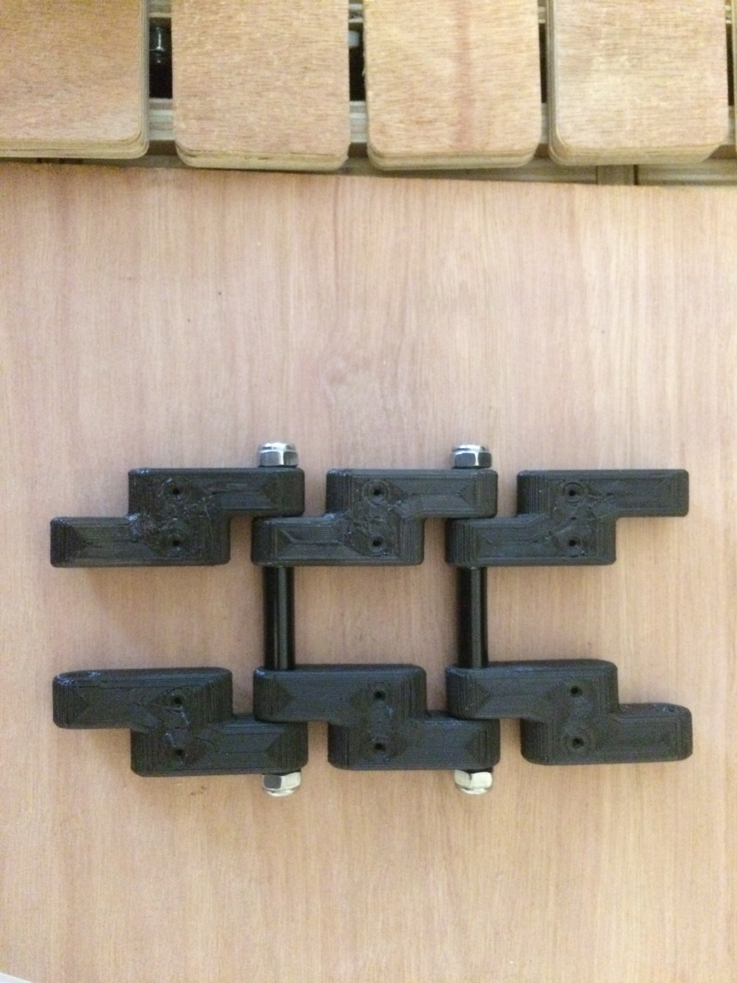
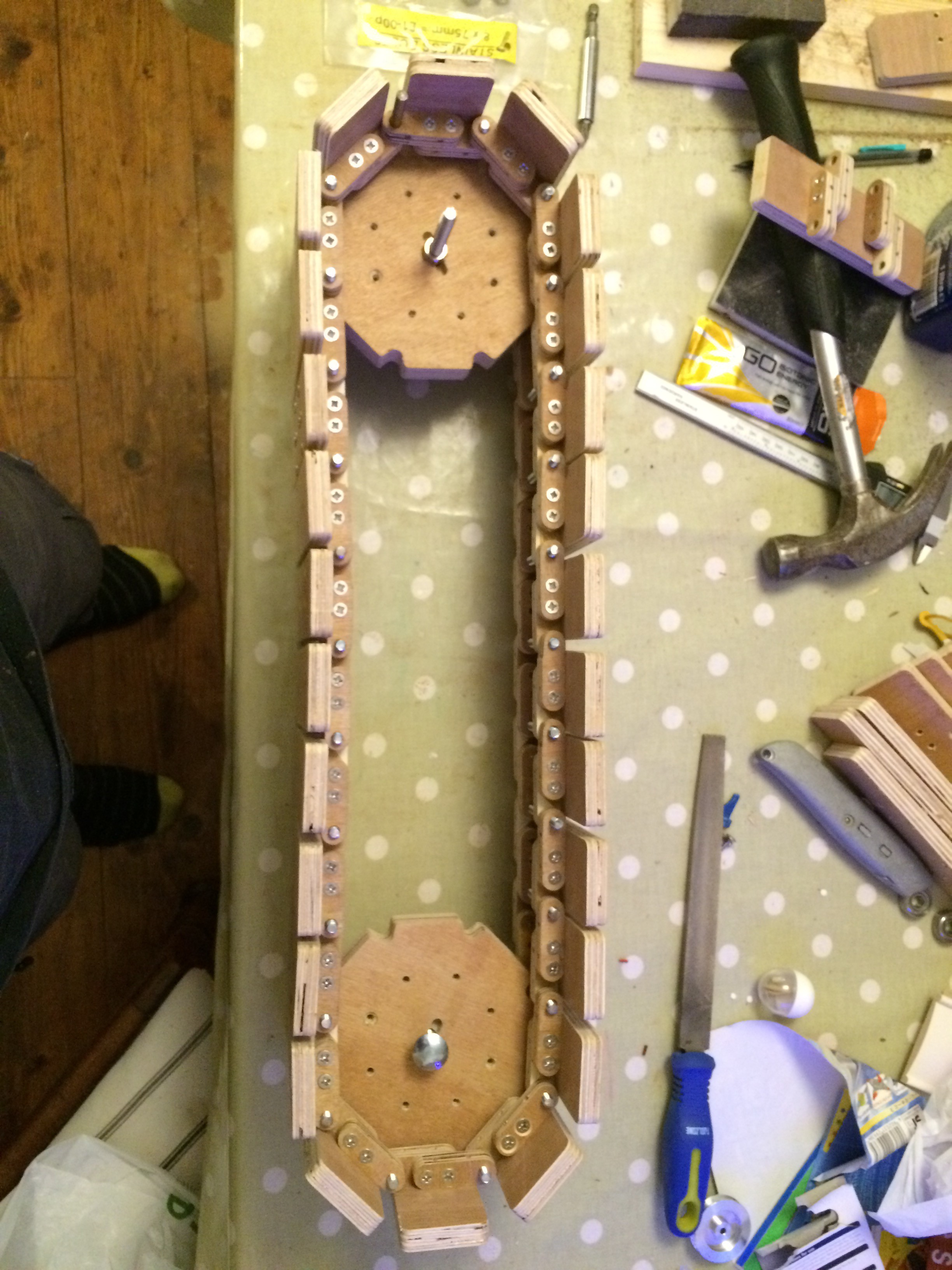
New track chain design. Note the nylon tubing to the 6mm threaded bar and the nylock nuts each side. The Track paddles fix to the chain with 2 screws per paddle. They seem to be firmly fixed.
Now i was confident with the new design time to machine all the parts and put it together...

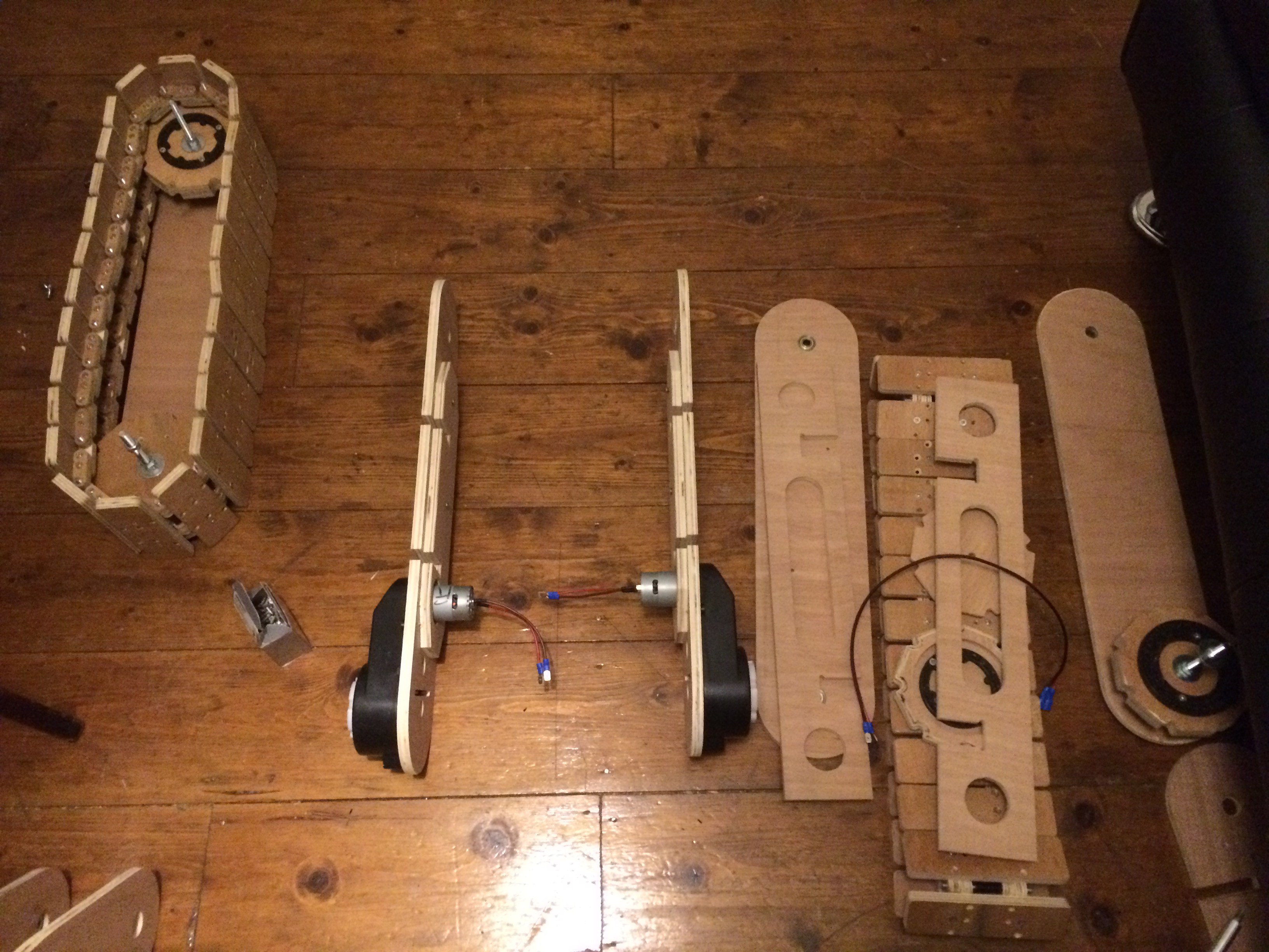
Bits and pieces bits and bobs put them all together and what have you got?
New drive wheels, note the bevels and the 3D printed Power Wheels coupler..
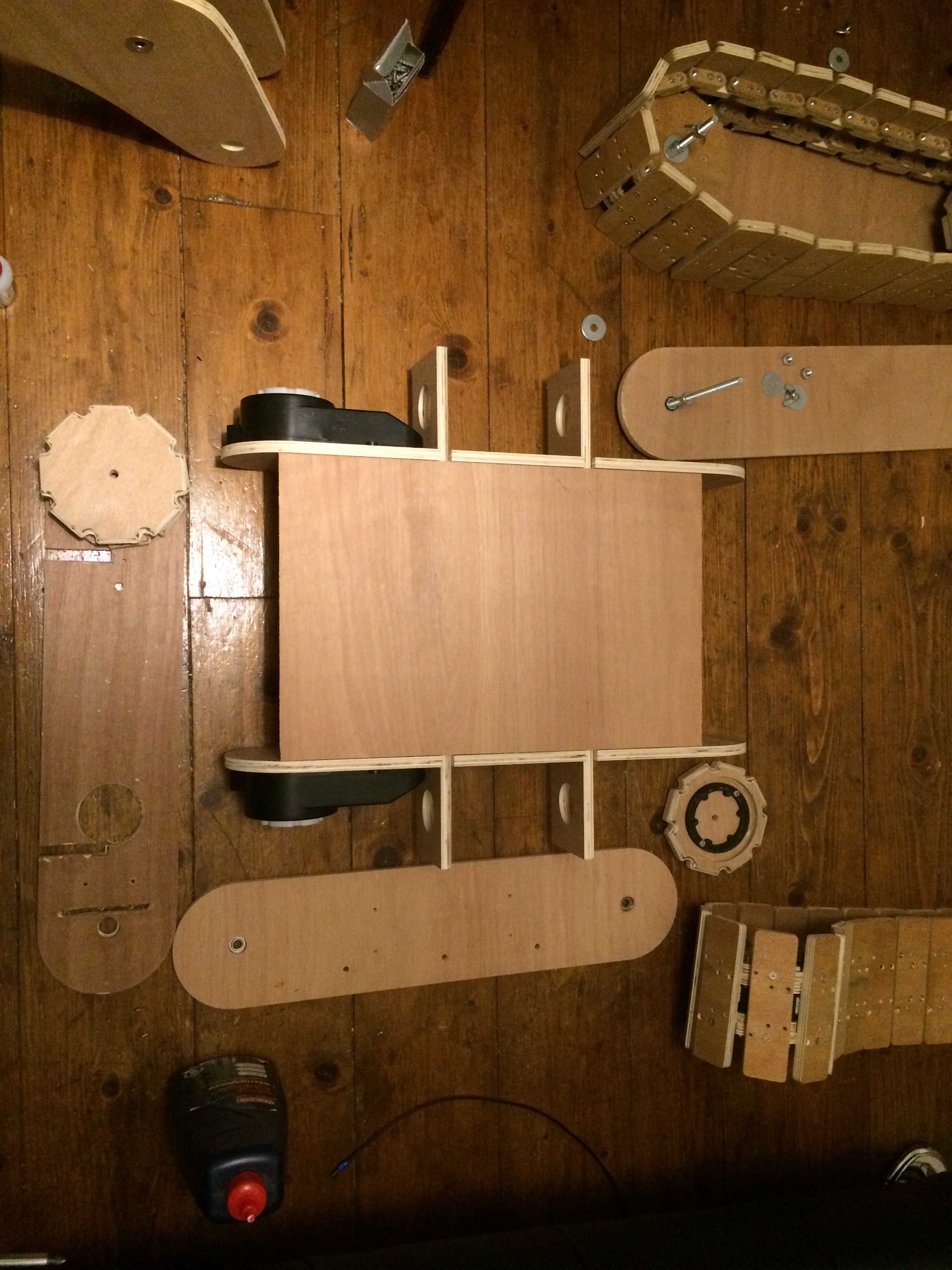
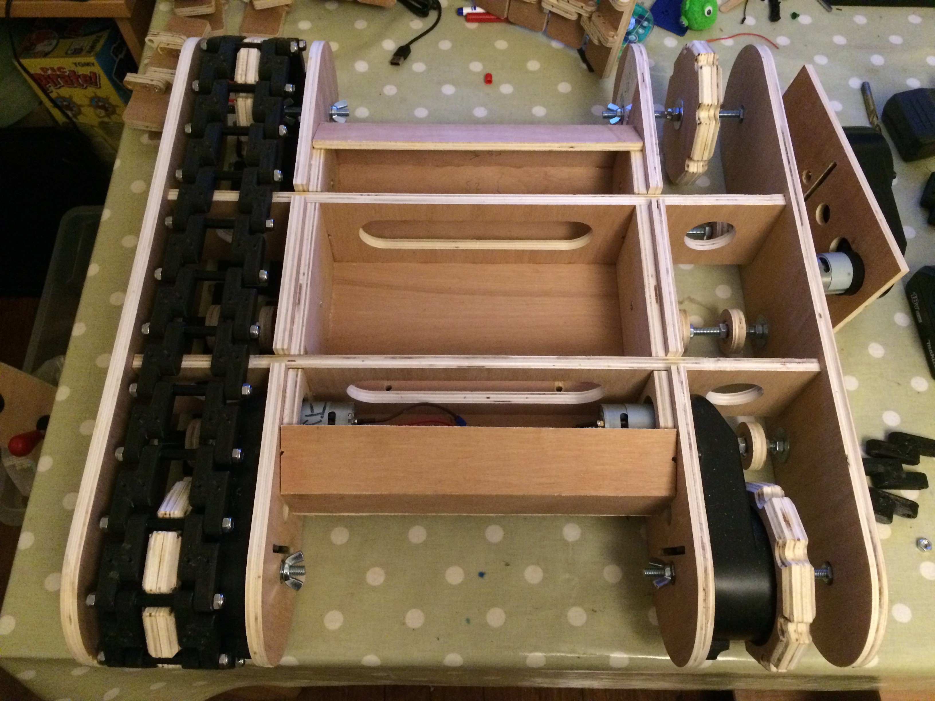
Cross braces and dry fitting box work to enclose the centre section
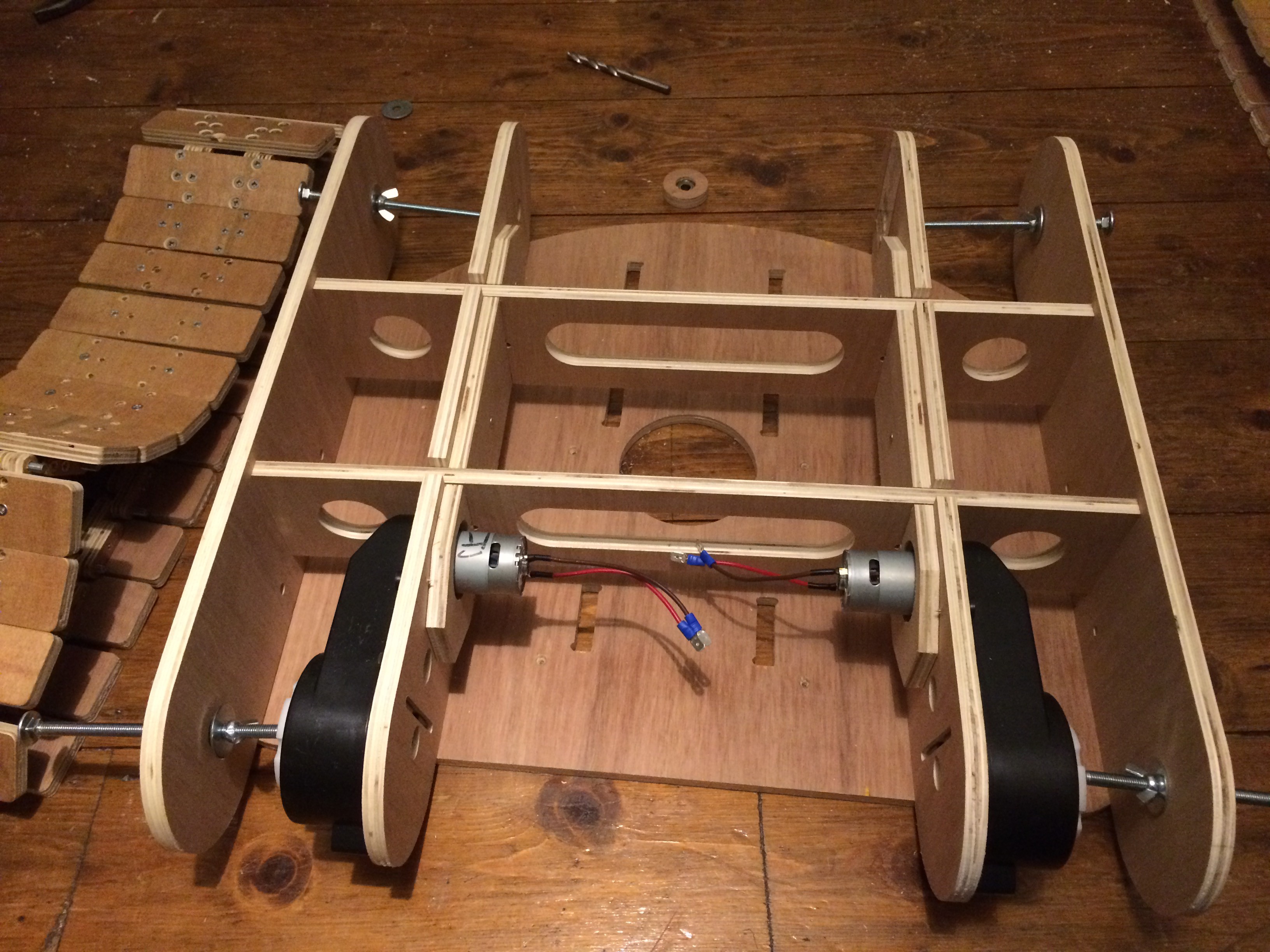
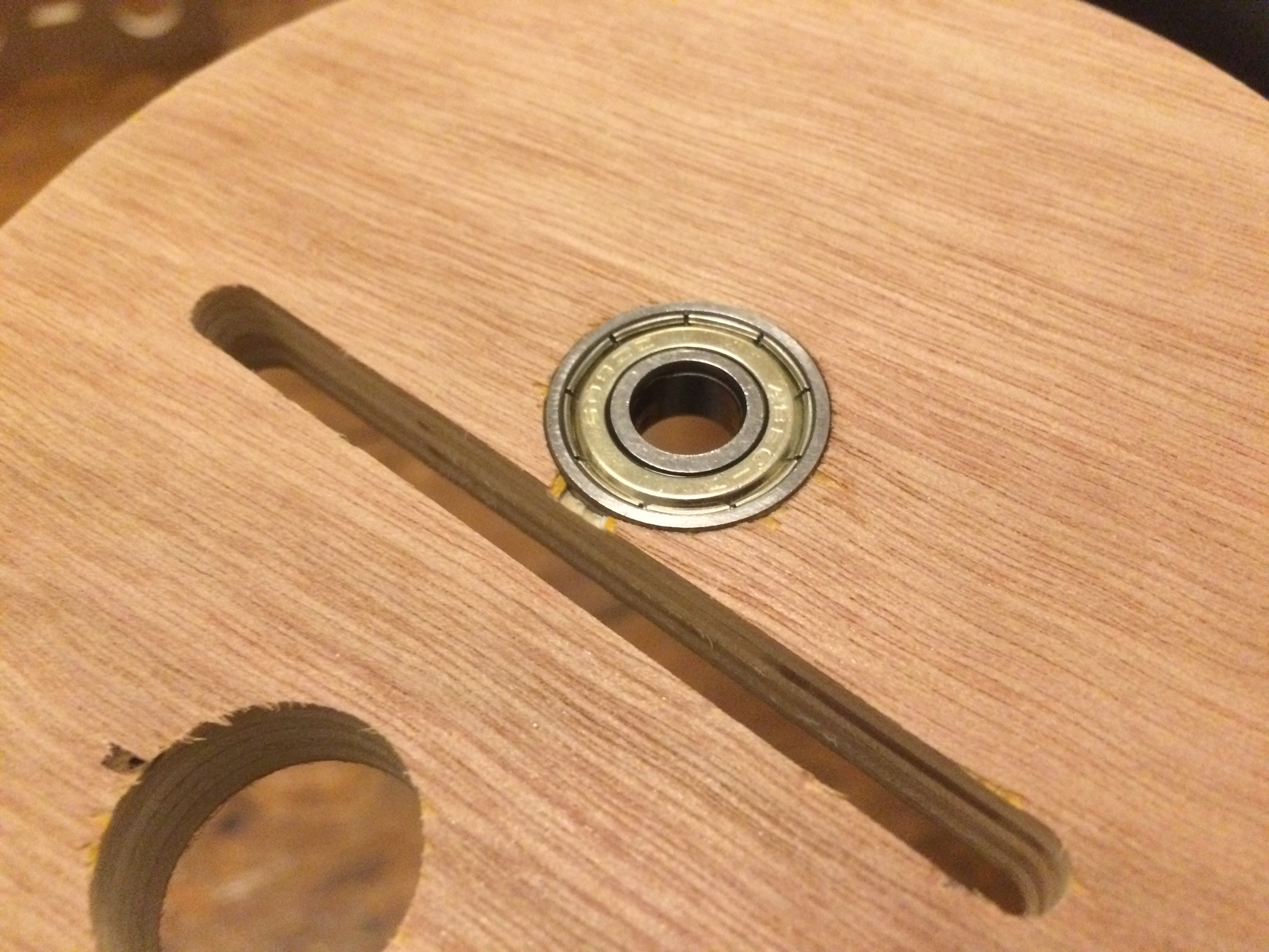
Track frame taking shape. Note the 8mm coach bolts used to support the drive wheels. Every pivot point has a 22mmOD 8mmID skate bearing.
Assembled drive wheels and idlers. The idlers also have a bearing each.

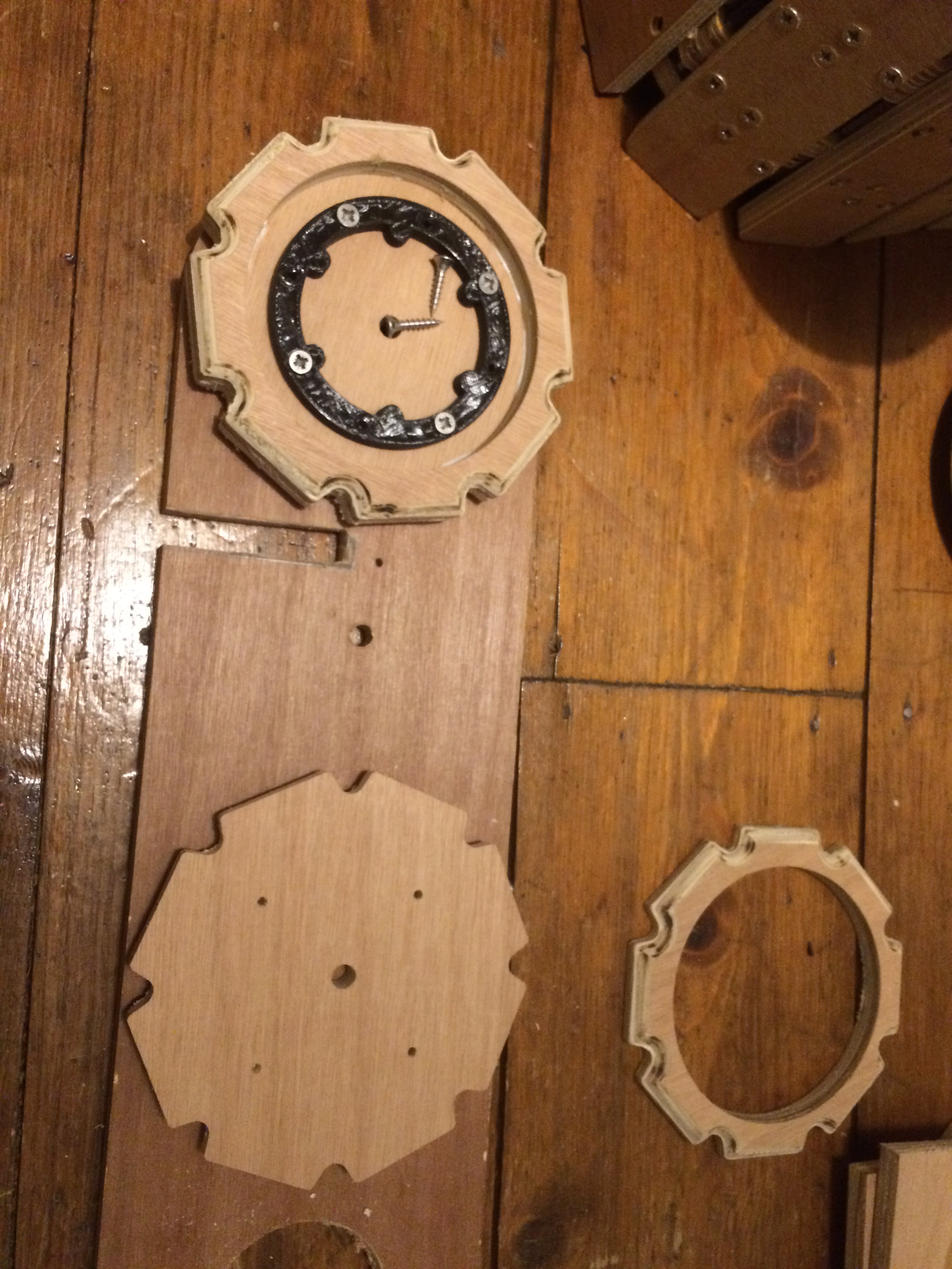
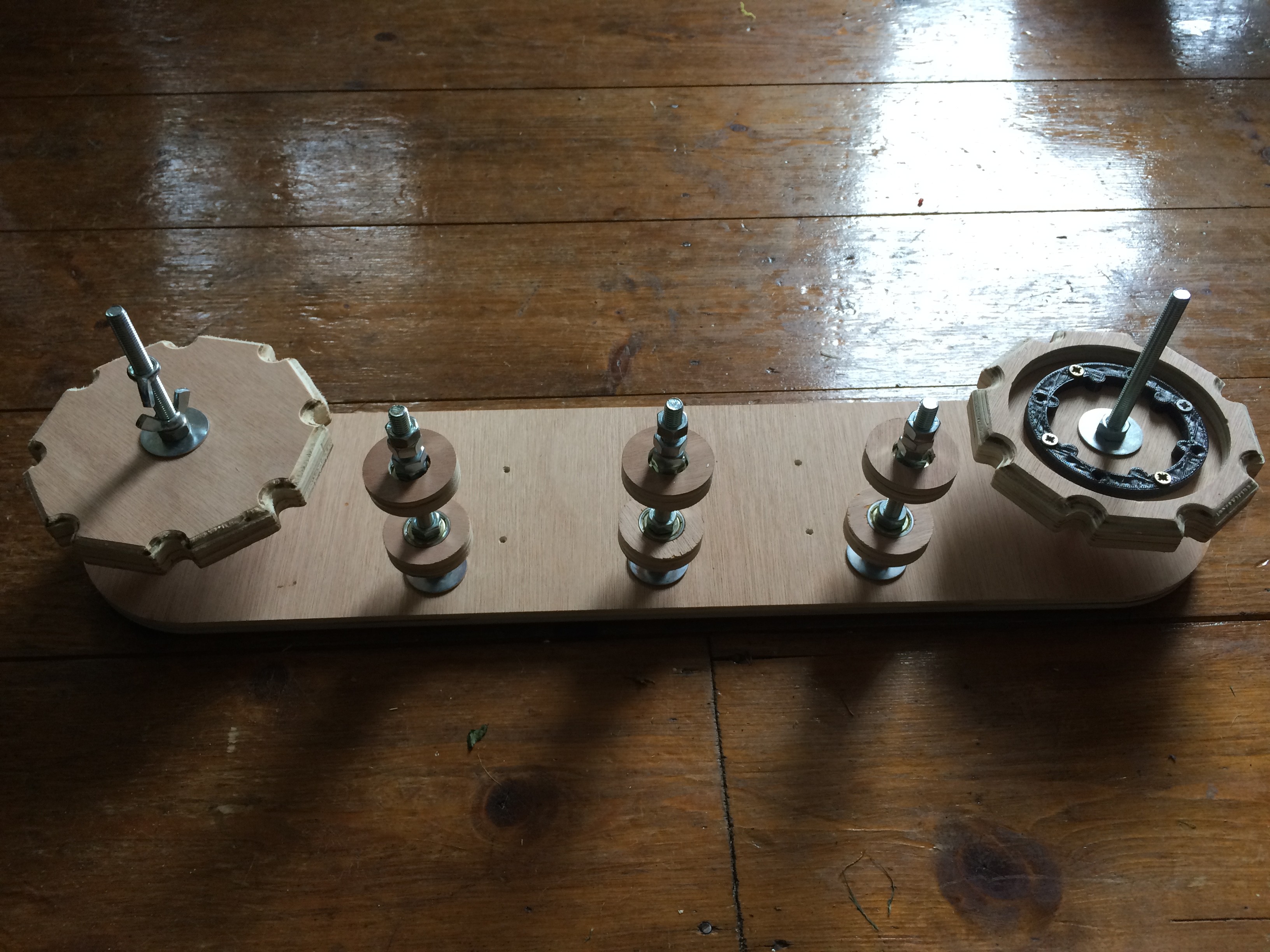
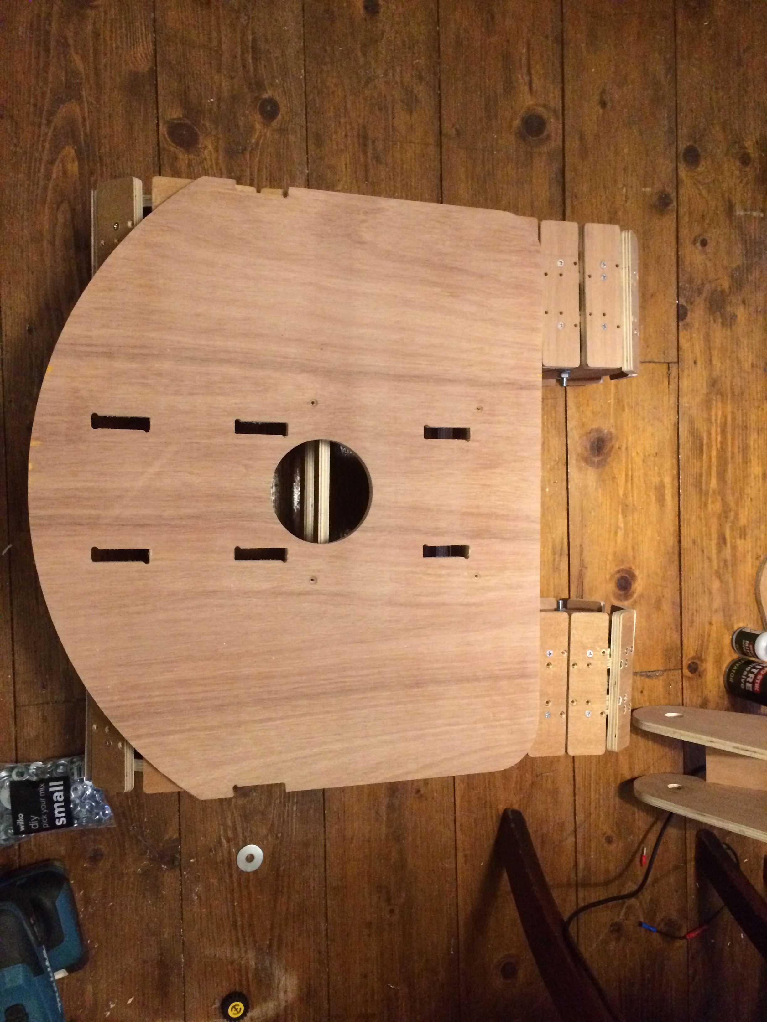
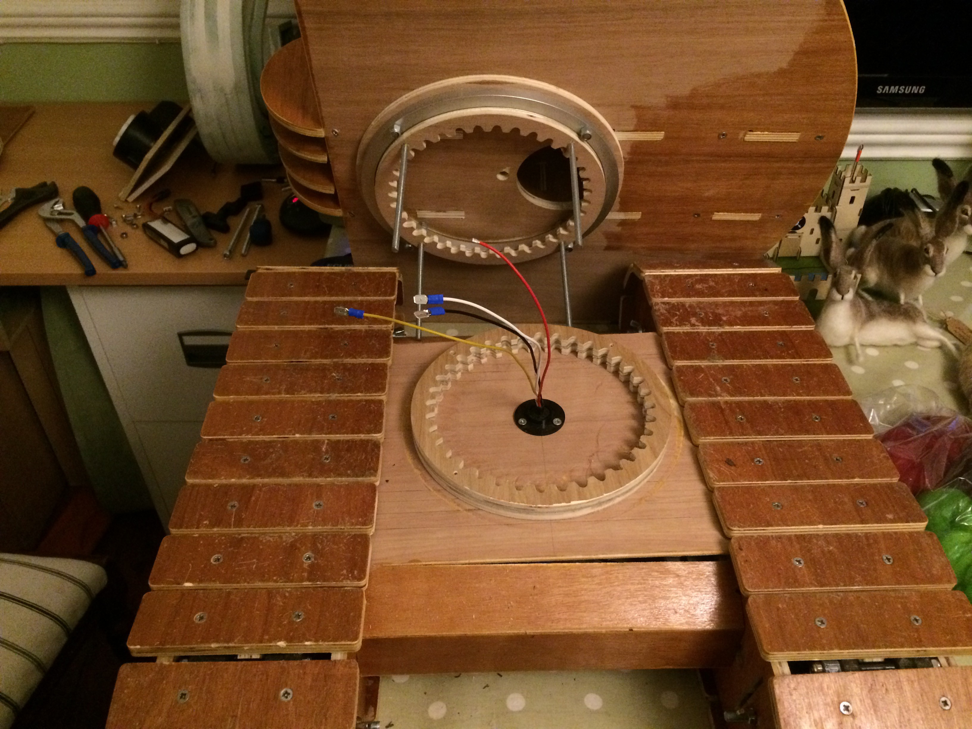
More assembly... Note the 4 holes in the centre plate. This take 6mm threaded bar right through top to bottom to firmly bolt through the Lazy Susan and the Slew Gear.
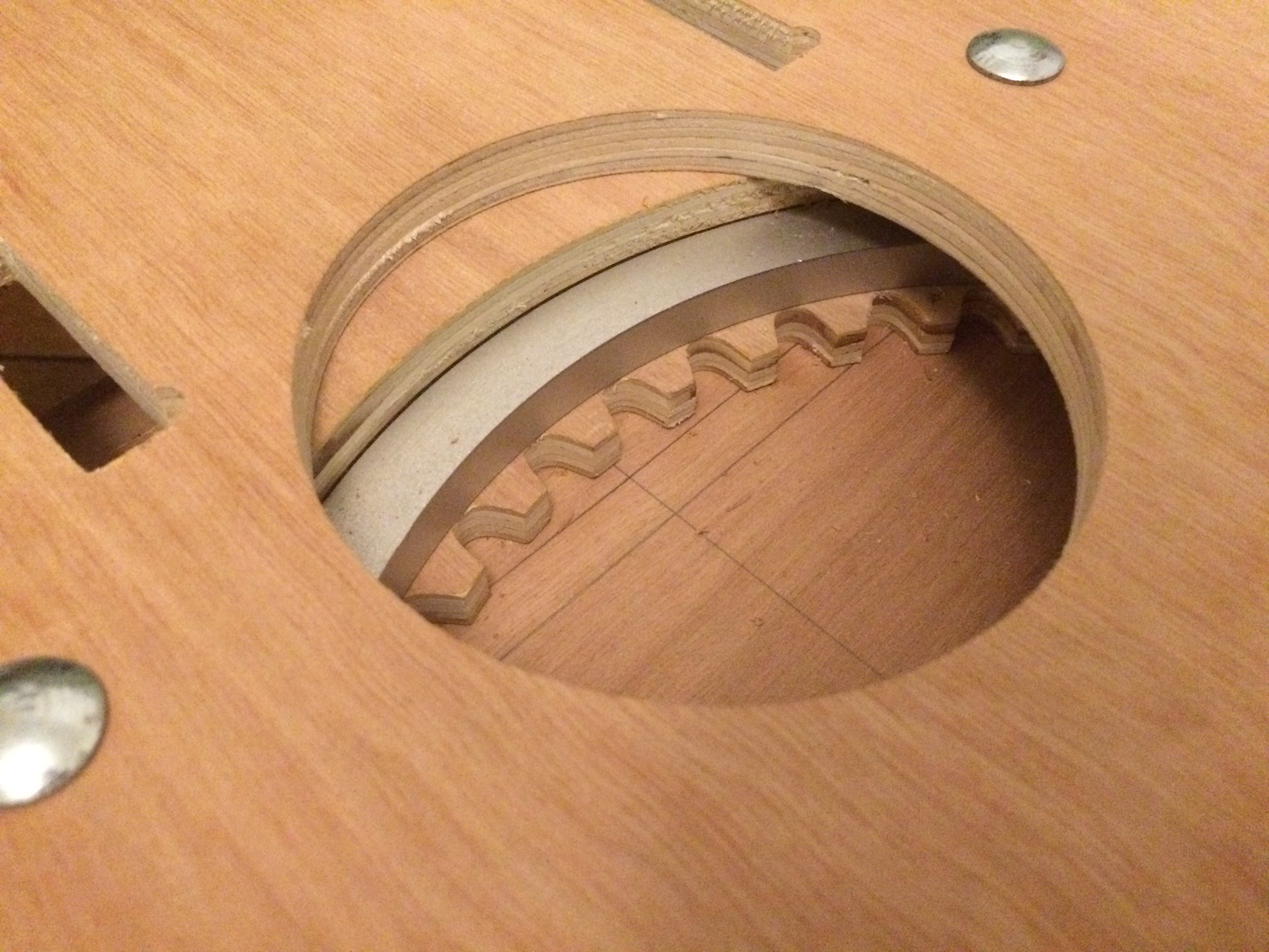
View through gap in top plate to slew gear below. The outer ring of the lazy suzan is fixed to the upper body and the inner ring is bolted through the slew gear right down through the centre section of the caterpillar track assembly below. The drive gear for the slew goes into the hole and meshes with the slew gear below. Spin Spin Sugar!
One chain on.
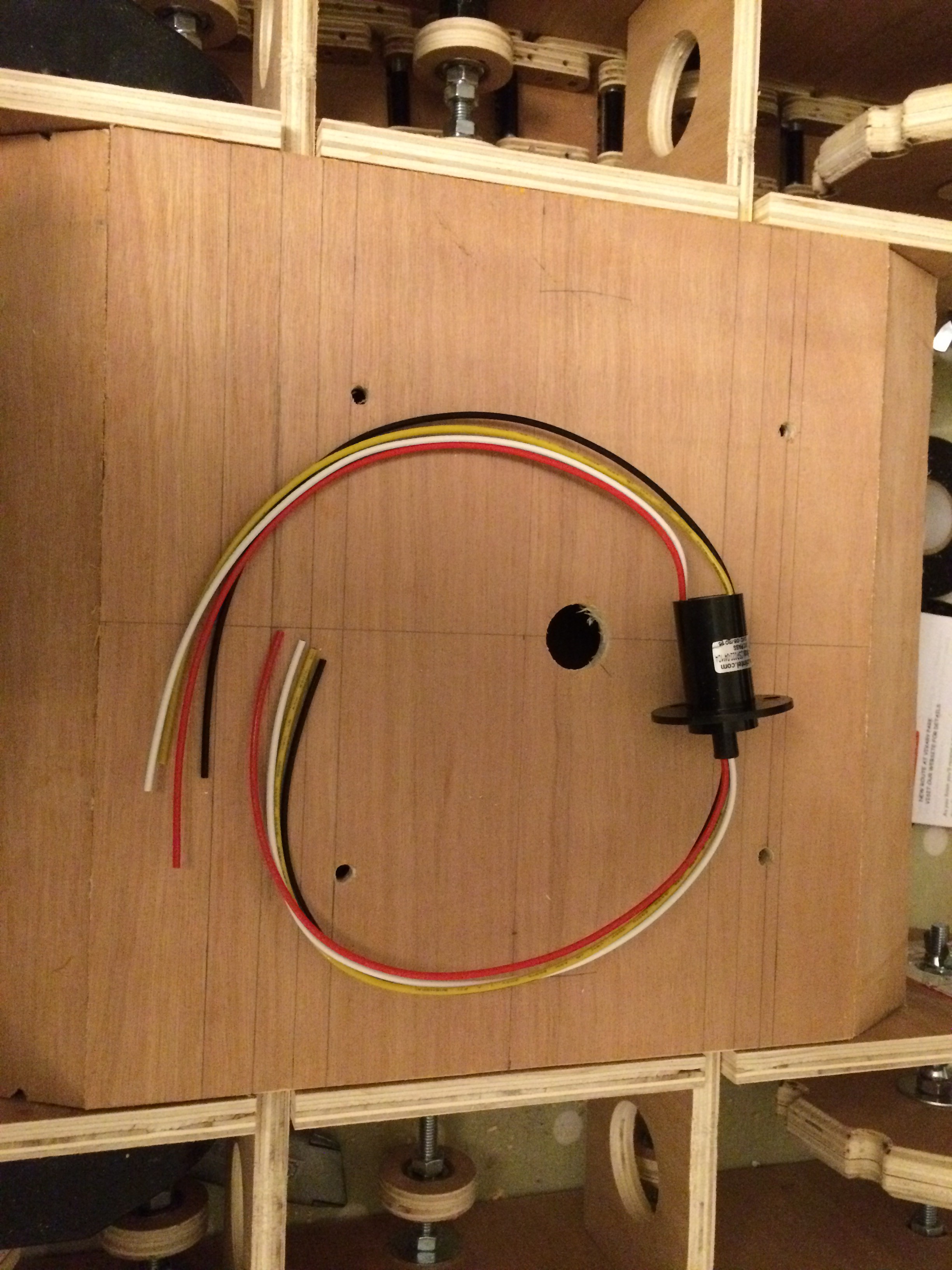
Slip Ring - I wanted the top part of the excavator to be able to freely spin continuously in both directions 360 degrees whilst maintaining power to the tracks below. A slip ring as you likely already know sorts out this problem.
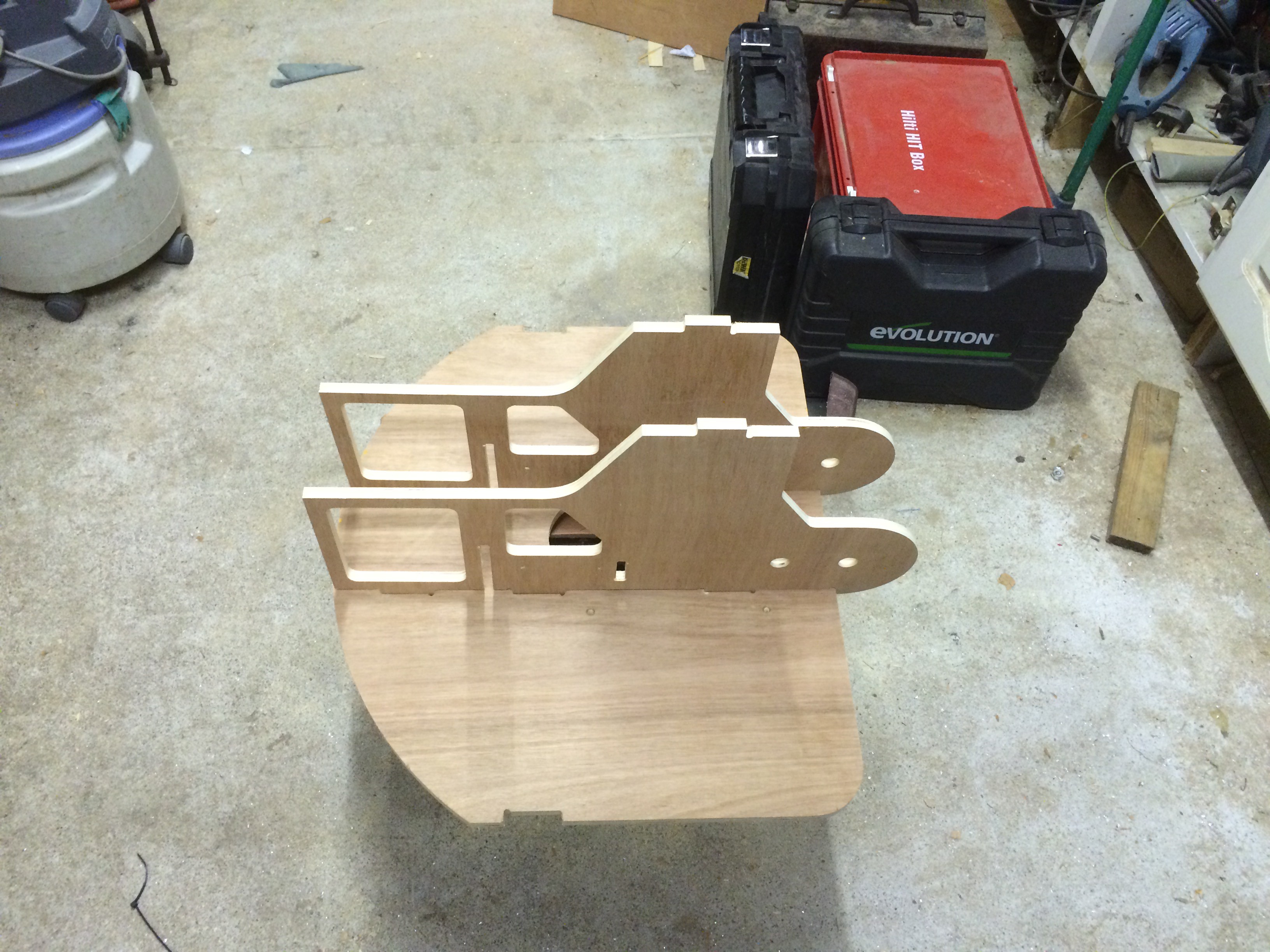
So Ive explained a lot about the design and assembly of the tracks but nothing about the counter weight, controls and the business end the bucket and arm. The above photograph shows the base plate for the counter weight.
The image below shows the base plate, cross braces and side panels for the counter weight in blue, the slew gear and lazy suzan in red, the mount for the slew gear box in green and the seat in white. The Gearbox is in cyan.
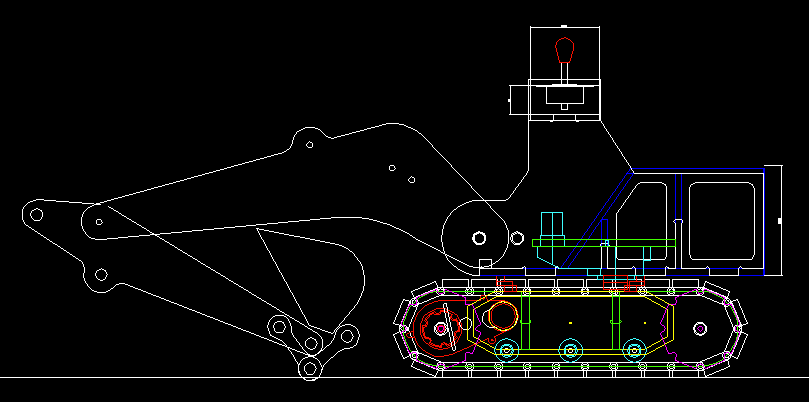
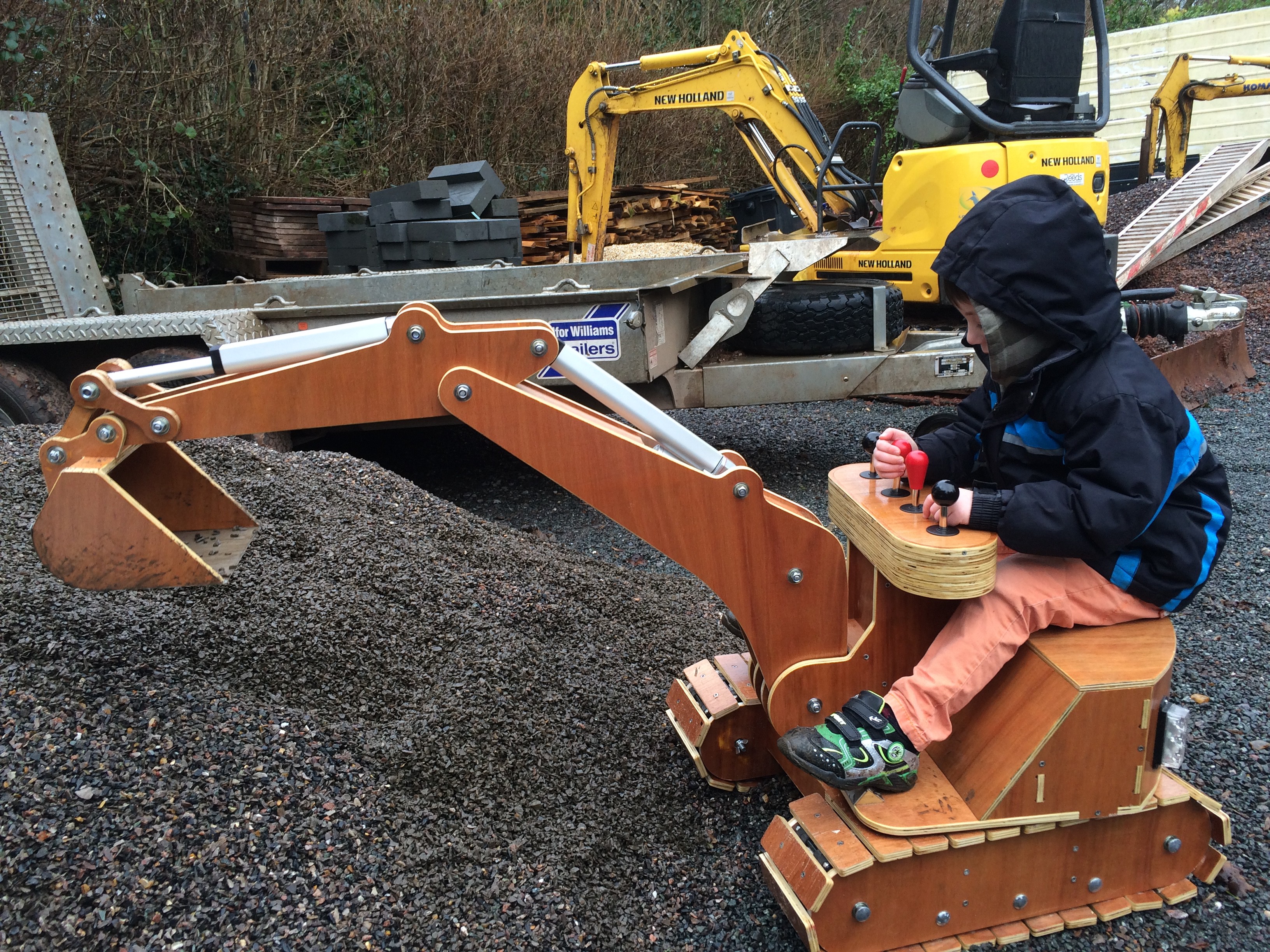
The image above shows the excavator in its entirety. The box work for the counter weight was fairly simple. I wanted a child to be able to sit on the counter weight and have their feet resting on foot plates just over the tracks and have the controls in easy reach.
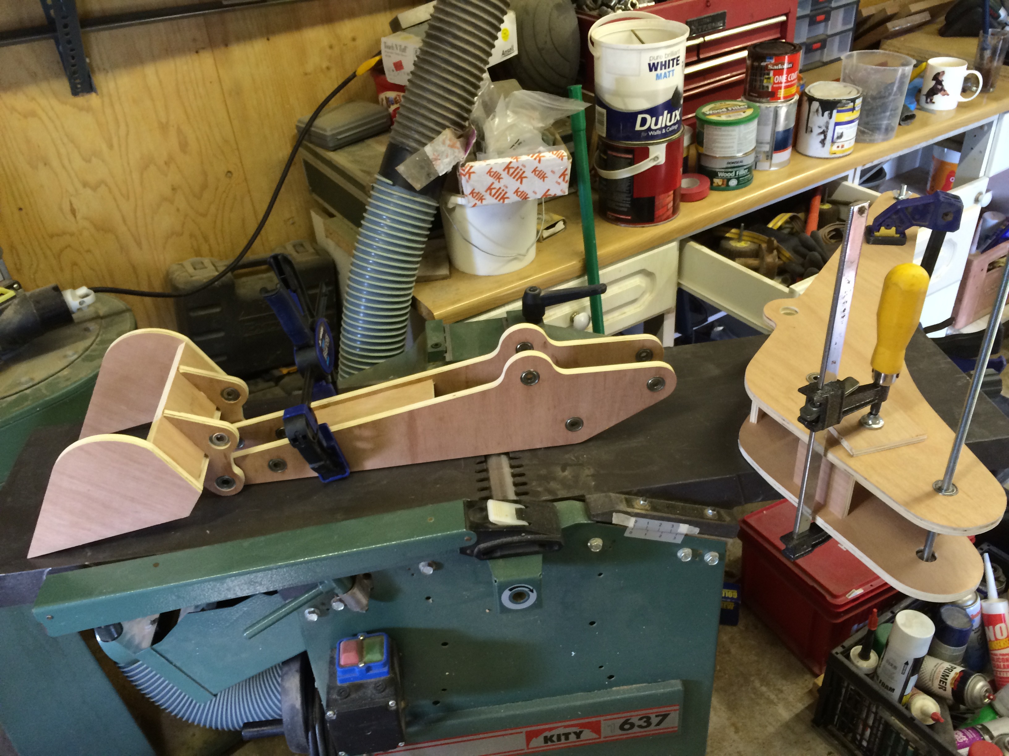
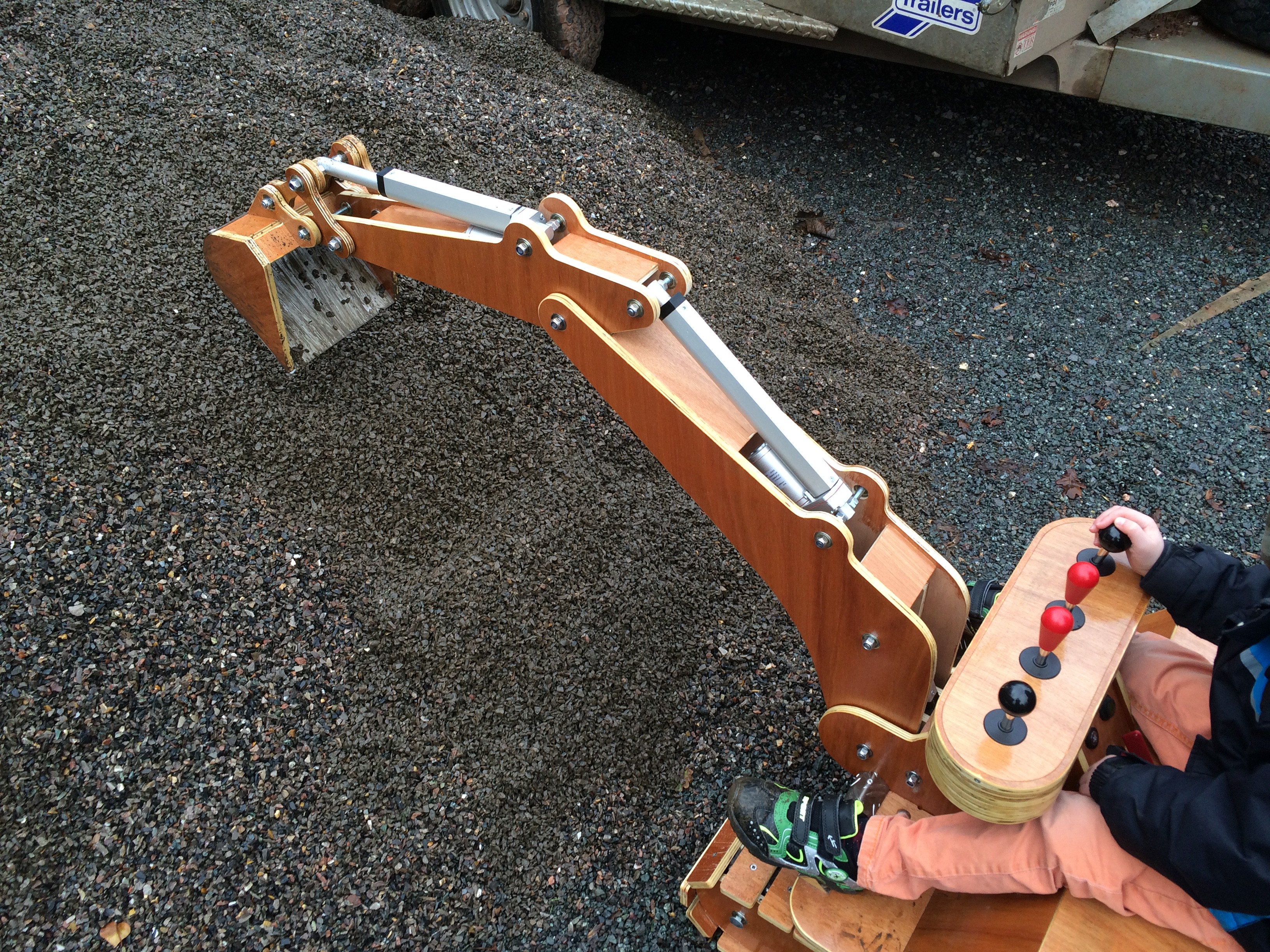
Next I needed to work out how to make the bucket, tipping link, dipper arm and boom function just like a real digger.

I worked out the full range of motion for the arm then worked back from there.
I decided that hydraulics and pneumatics where way to complicated and that the best and cheapest option would be linear actuators. I managed to find some reasonably cheap 12v actuators. The ones I purchased are for opening windows on buildings and as such have a scary pull and push force. From memory I think they can pull 60kg and push 100kg!
SAFTEY!!! - Obviously giving a small child access to that amount of potential crushing force is dangerous and downright irresponsible so I needed to think of a way to reduce the risk. All the gaps and pinch points have been reduced to the minimum so its difficult for arms and fingers to get trapped in the digging arm. Ultimately I opted for adult supervision when the excavator is in use.
If I had the money I would buy much faster actuators. Also I would buy shorter actuators and optimise the mounting lug locations to suit the throw of the actuator. More on that point later....
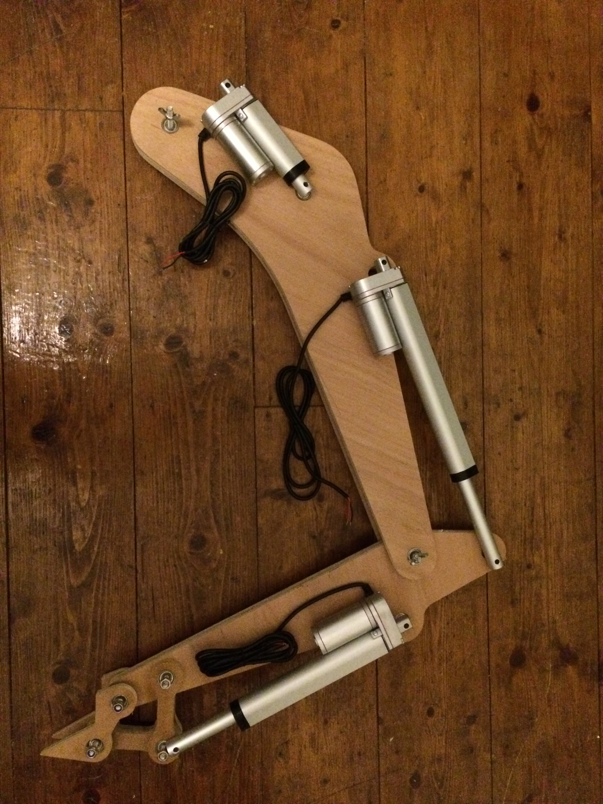
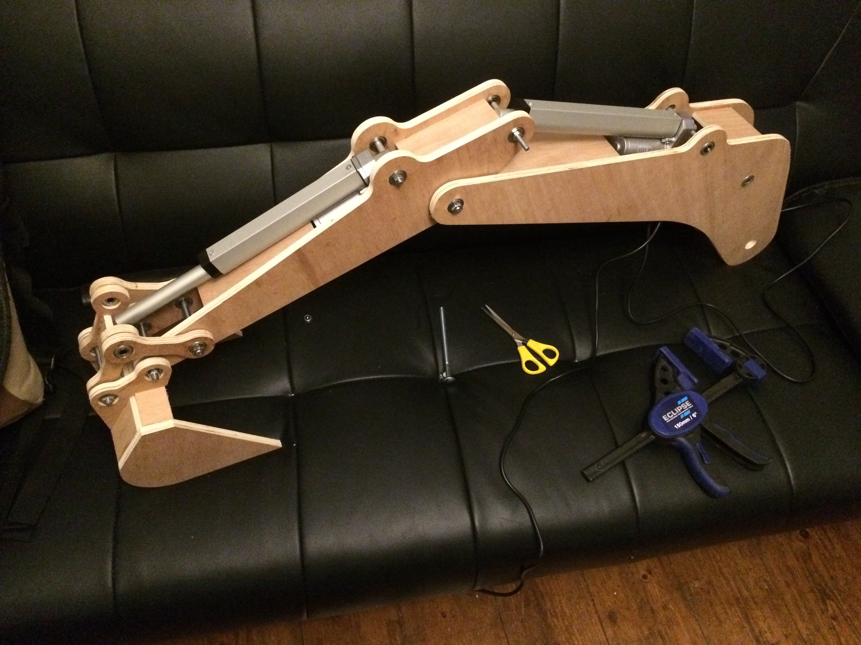
The above image shows all the linear actuators and the arm laid out for testing.
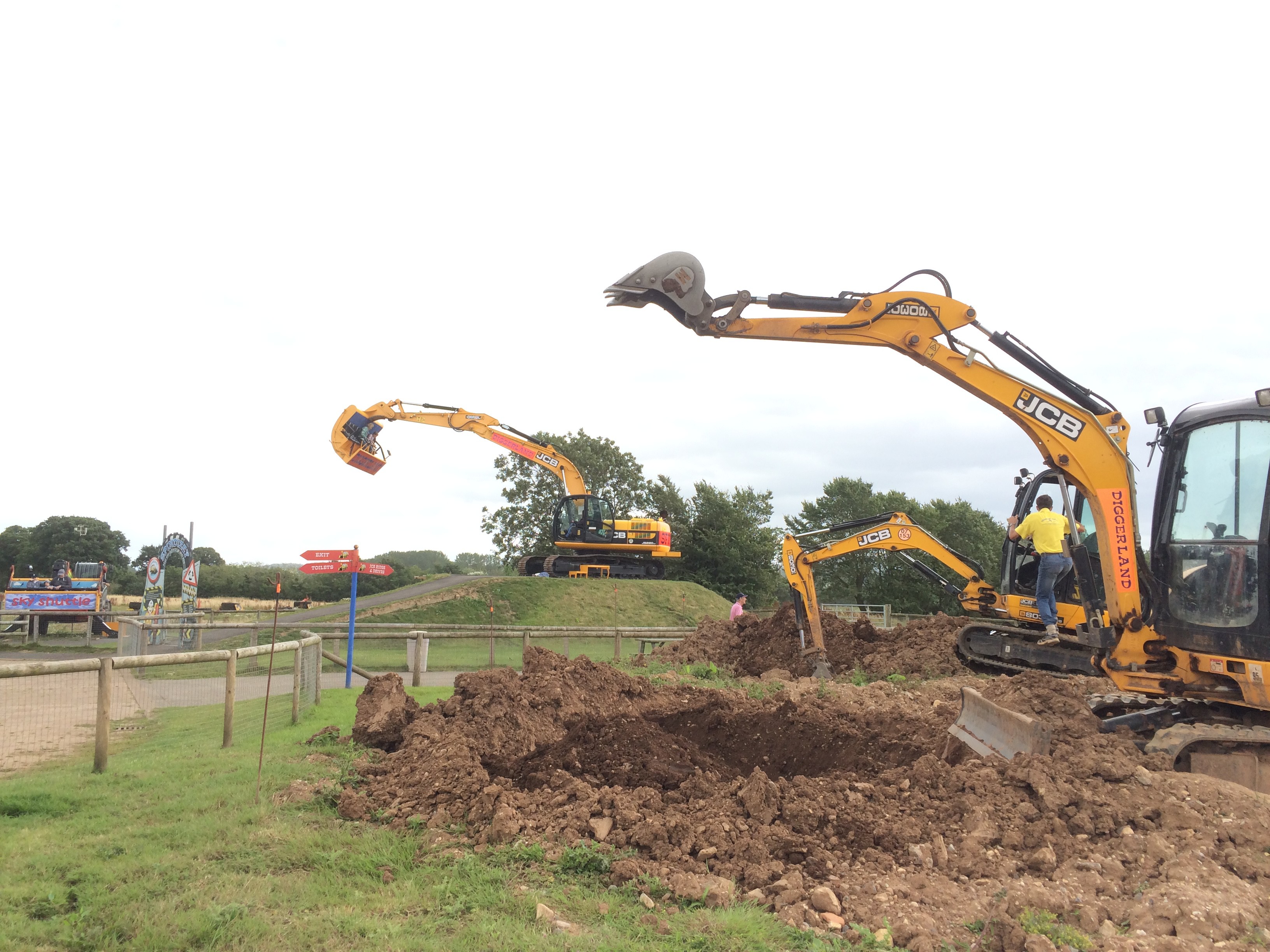
Image from the infamous DIGGERLAND!!!!
This video shows an actuator being controlled using an arcade joystick.. More on the controls later...
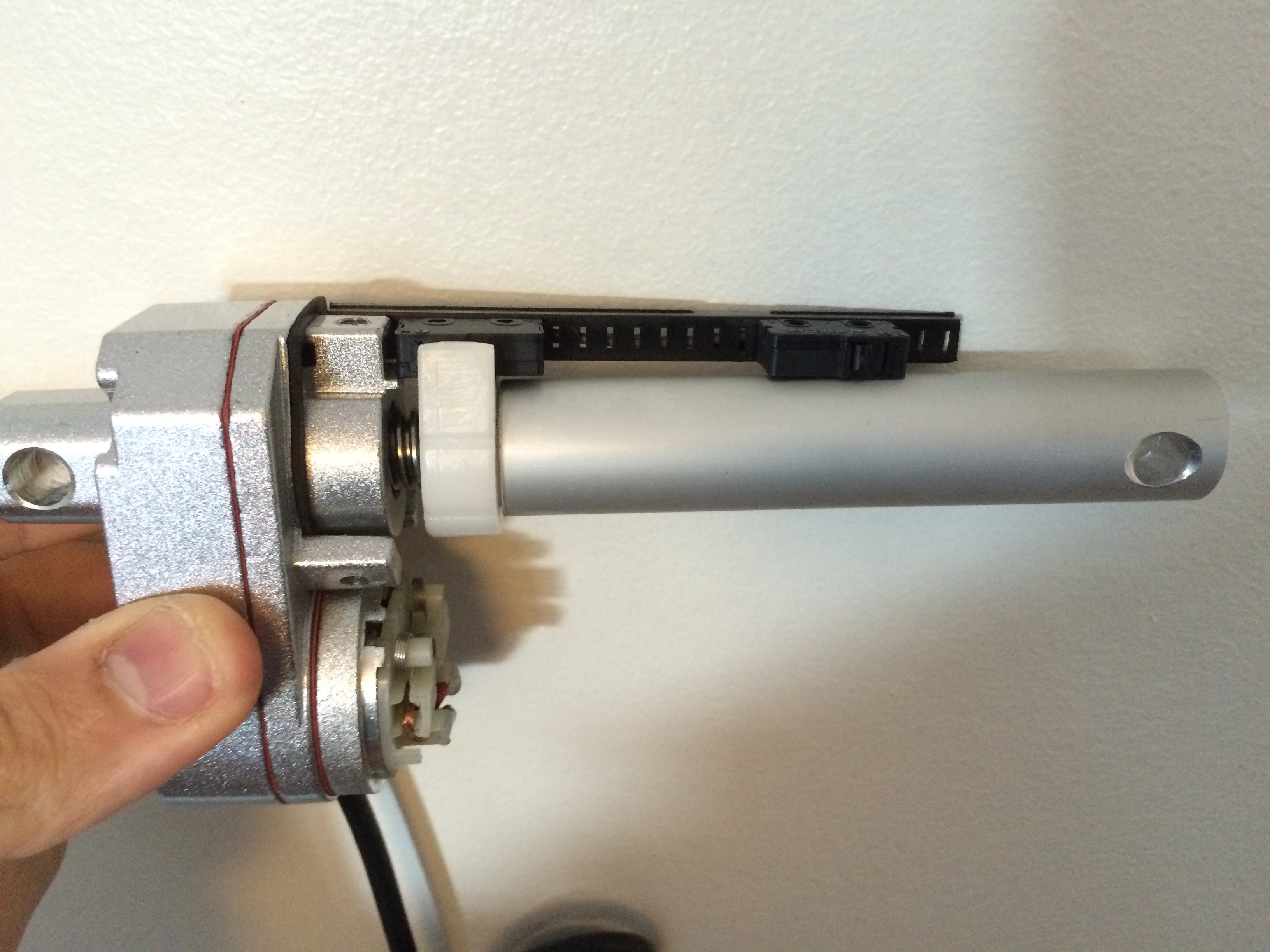
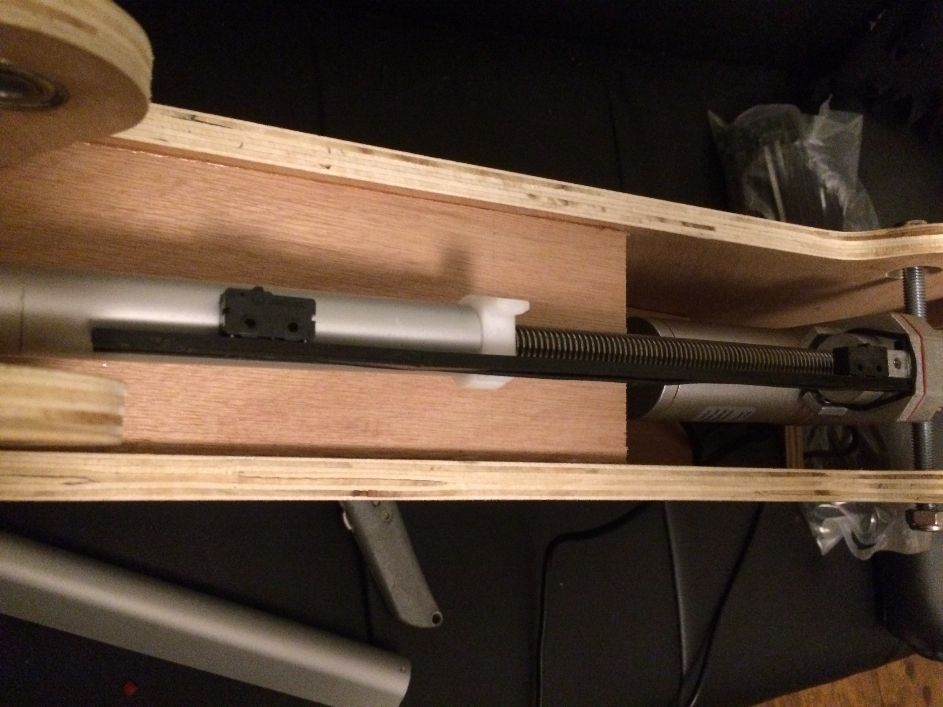
Now, because I'm lazy and thought that all linear actuators had simple end point adjustment I roughed out the mounting lugs and put them approximately in line with the locations of the real excavator. I thought foolishly that I could just trim the end points of the actuator to suit my lugs. WRONG!!! My pushers came with little end point microswitches that determined the end of the stroke both in and out. So... I had to mess about stripping them apart and moving the microswitches to suit my throw requirements PITA!!! Next time ill move the lugs in the CAD model to perfectly suit the throw.
The image below shows the boom actuator with the cover removed. Note the two micro switches and the white nylon that pushes the button.

Bucket taking shape.
Gluing an clamping...
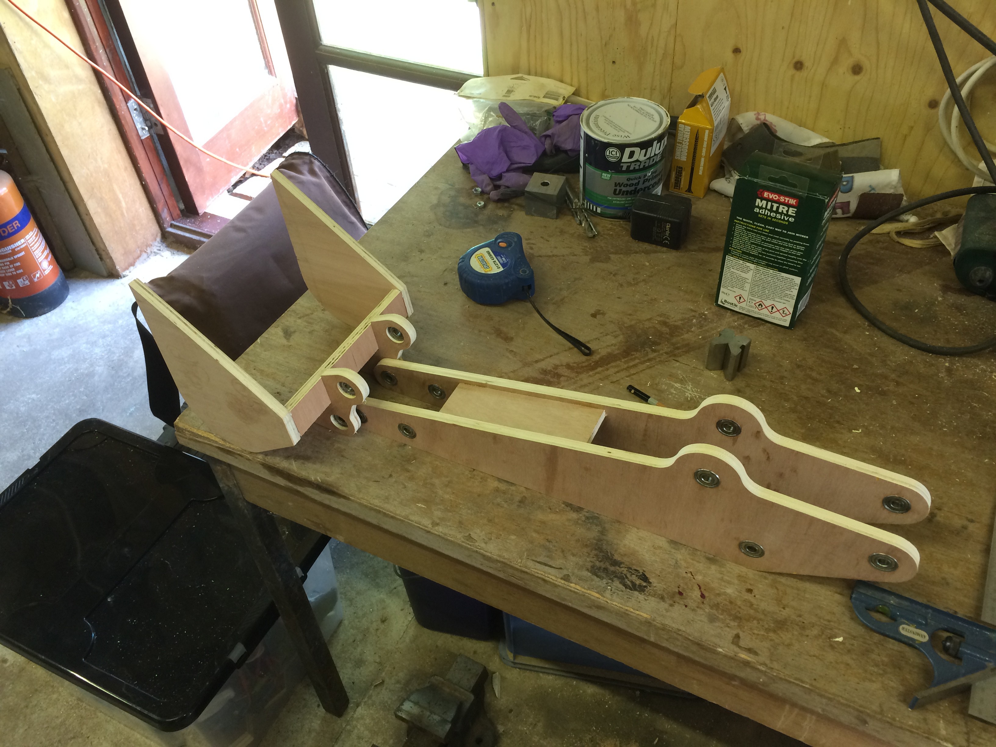
Dipper arm and bucket. 12mm ply for the sides and 9mm for the braces between.

Taking shape...

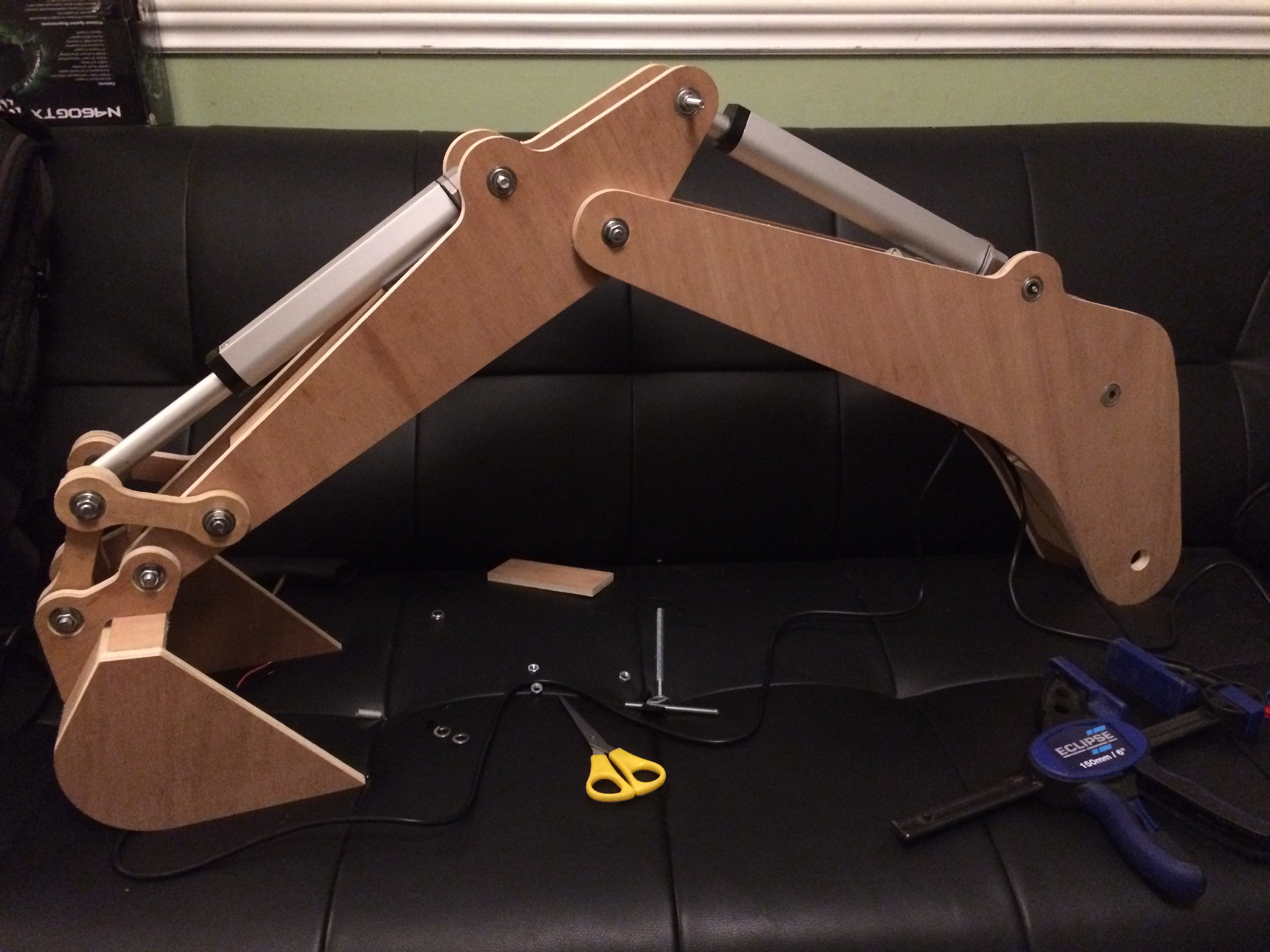
Out stretched.

Mounting the Actuators...
Nearly complete arm..
Shaawing!
Adjustments to the microswitch location.... Such a fiddly pain.
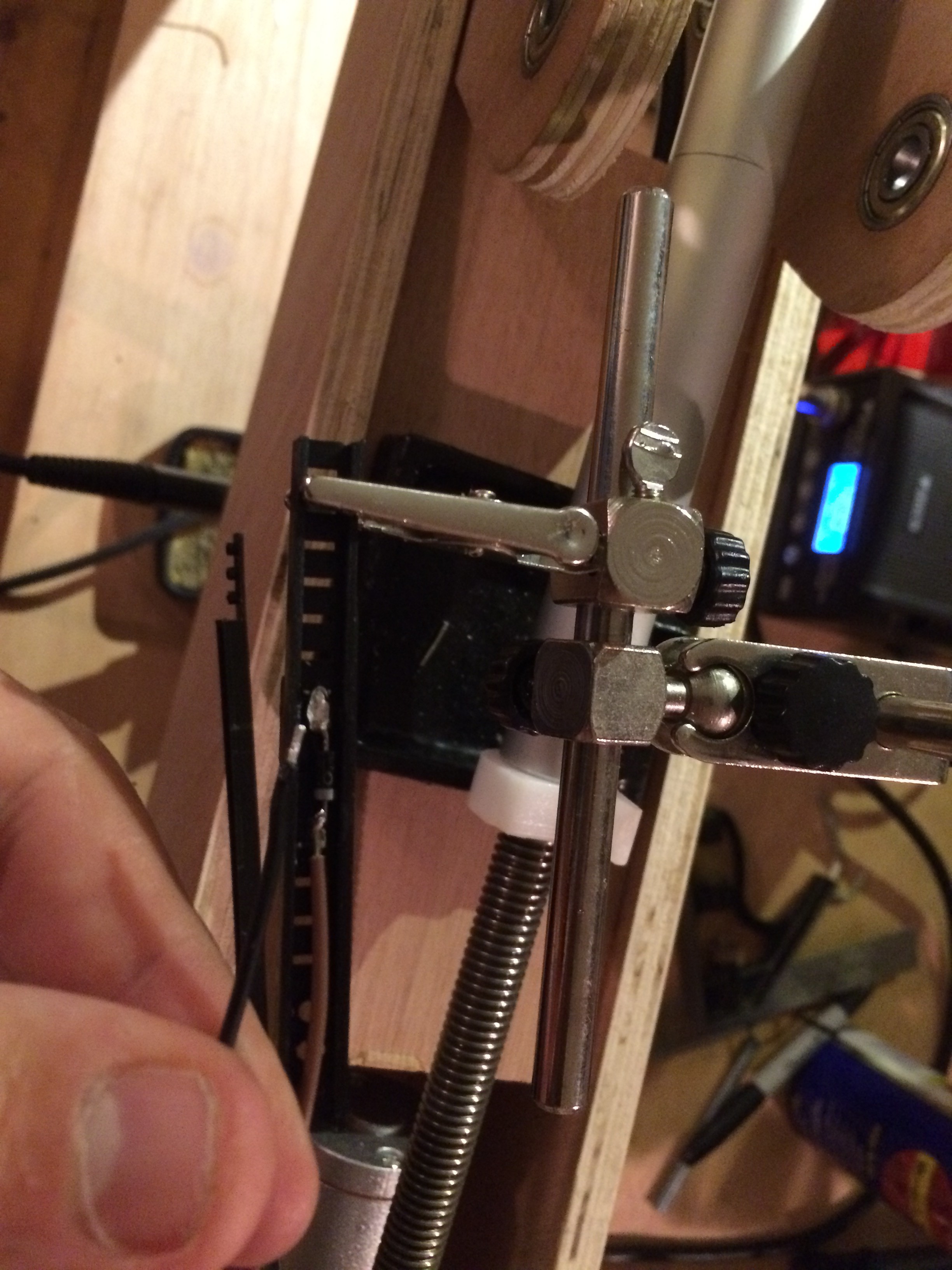
Surgery!
Electronics - Ok so i've been putting off explaining the electronics but the concept is pretty simple and really use full if your goal is to reverse the direction of a motor. The picture below was the best wiring diagram I could find to illustrate using two 5pin relays to swap the polarity with two switches. Google it theres lots of tutorials out there.
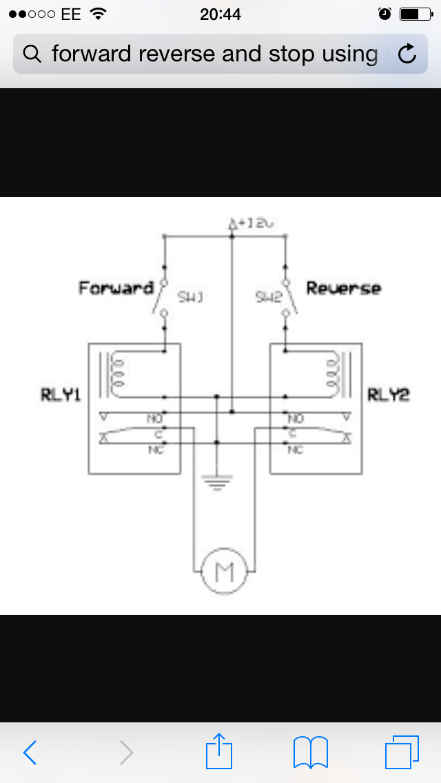
Relays - If your a seasoned hackaday reader then you don't need me to explain the purpose of relays. If not then essentially they are a way to switch a high current with a low current switch. This solution is perfect for arcade switches as they tend to only be capable of switching low current.
I chose 40A automotive relays as their cheap and readily available.
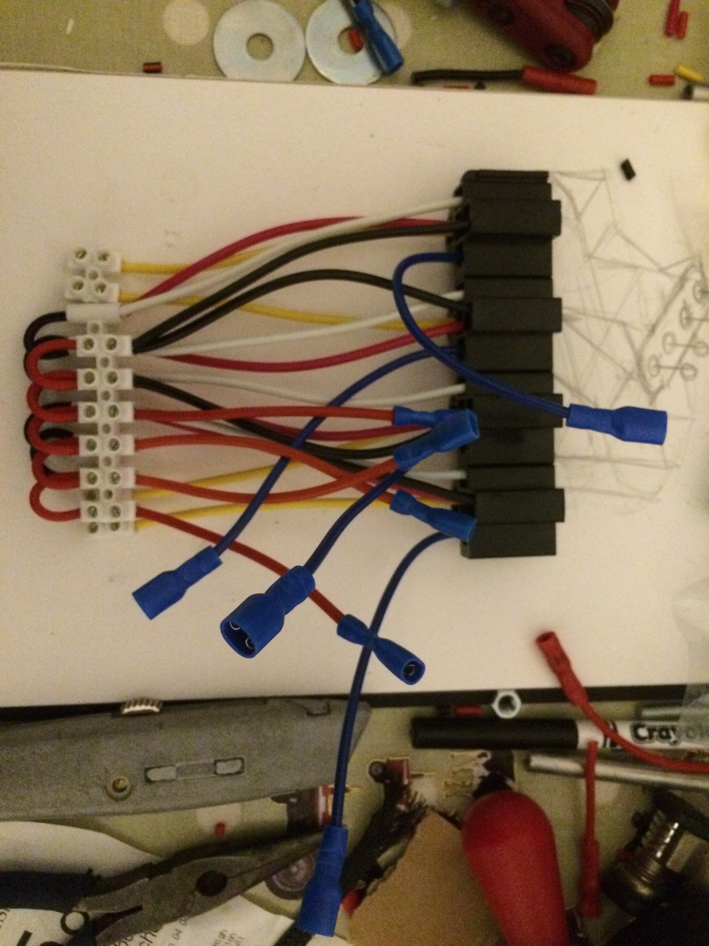
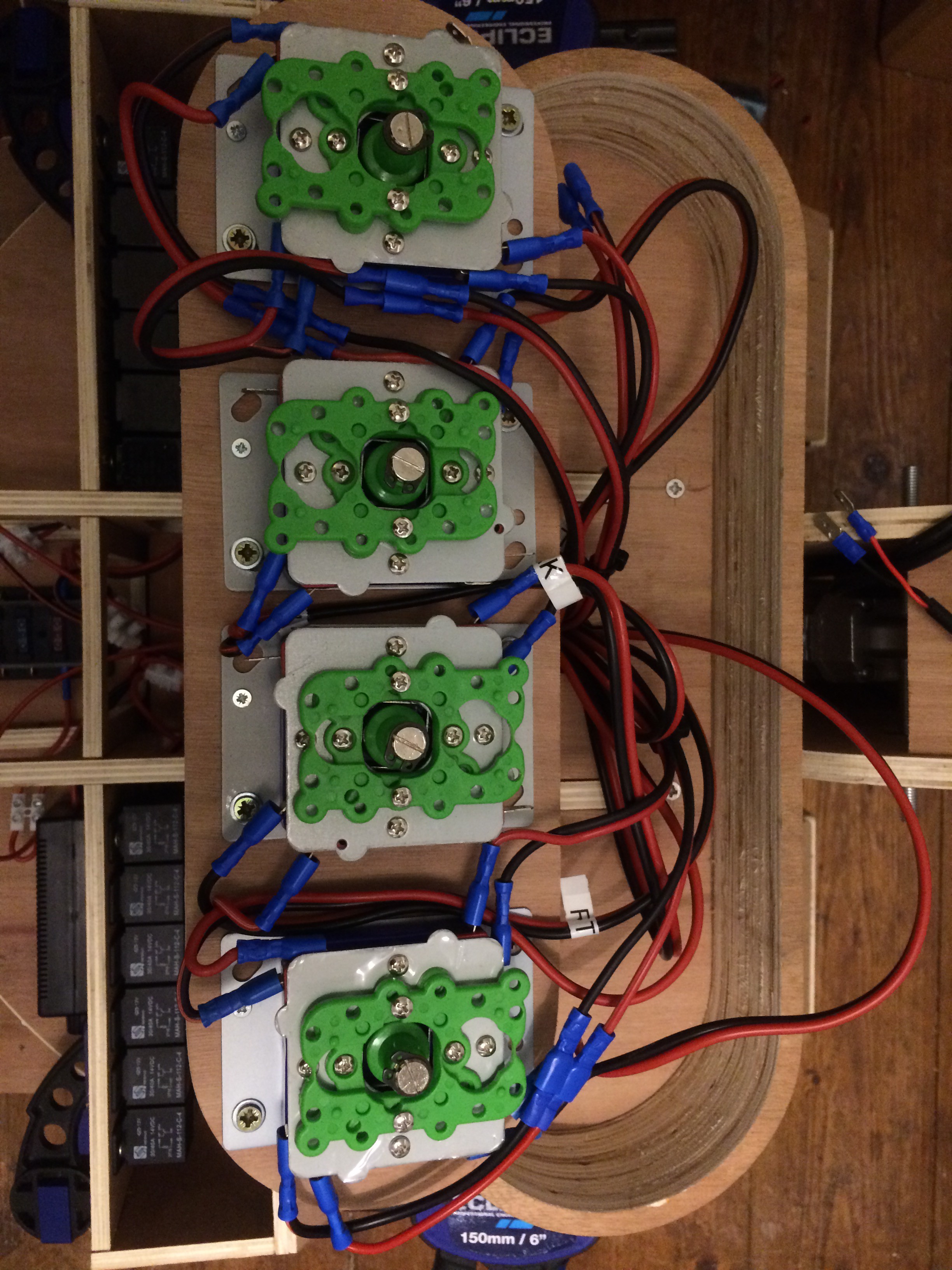
The above photo is of one wiring harness that operates the caterpillar tracks.
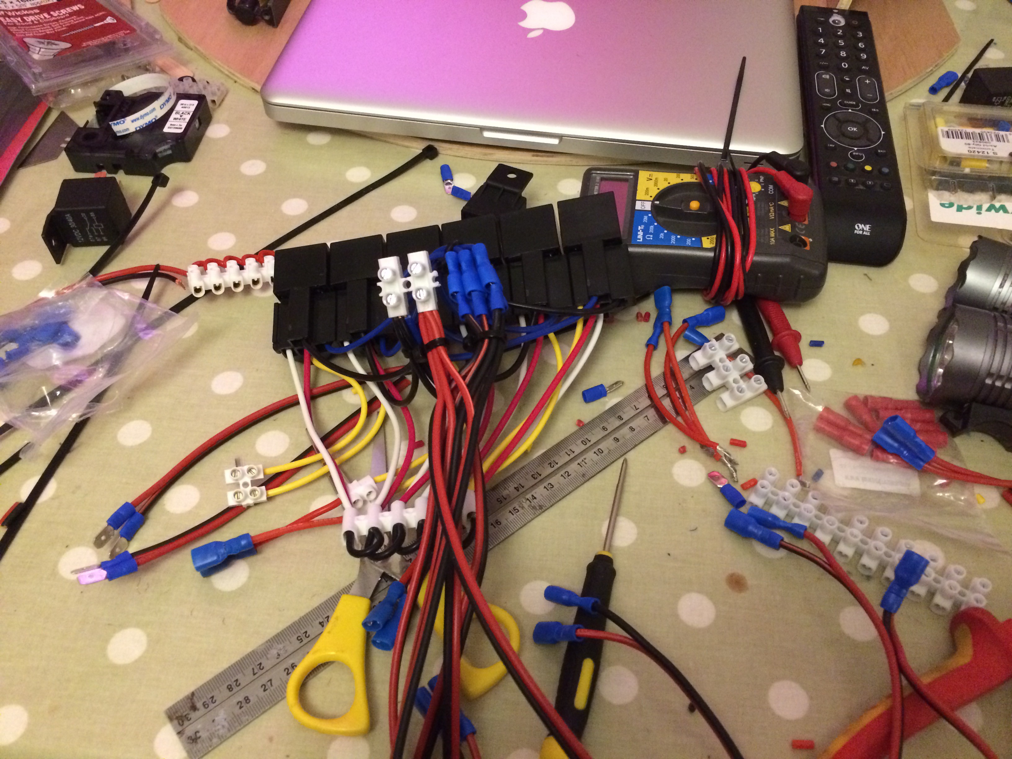
Nice clean workspace!
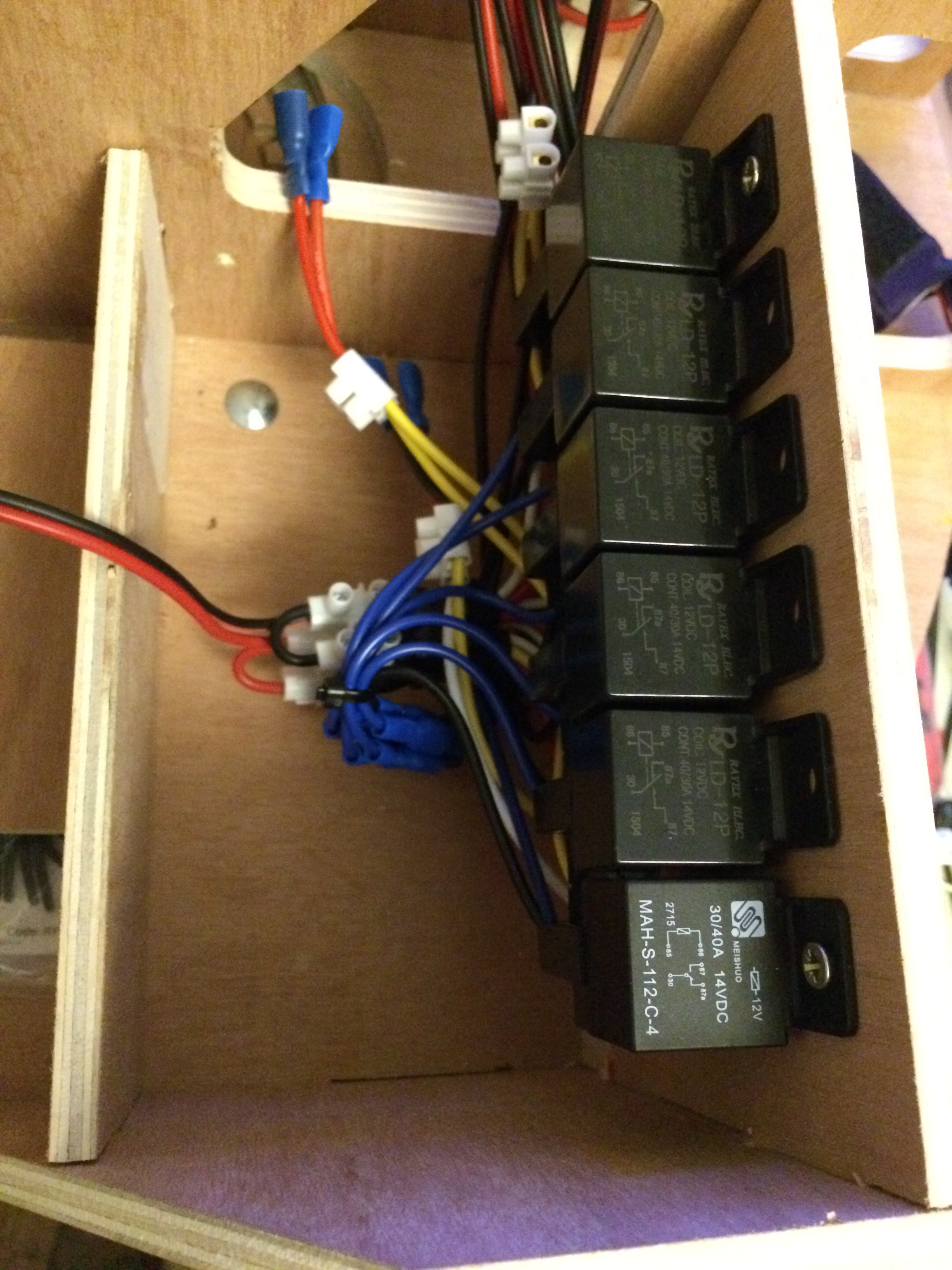
Mounting one set of relays into the counterbalance. 3 pairs on each side.
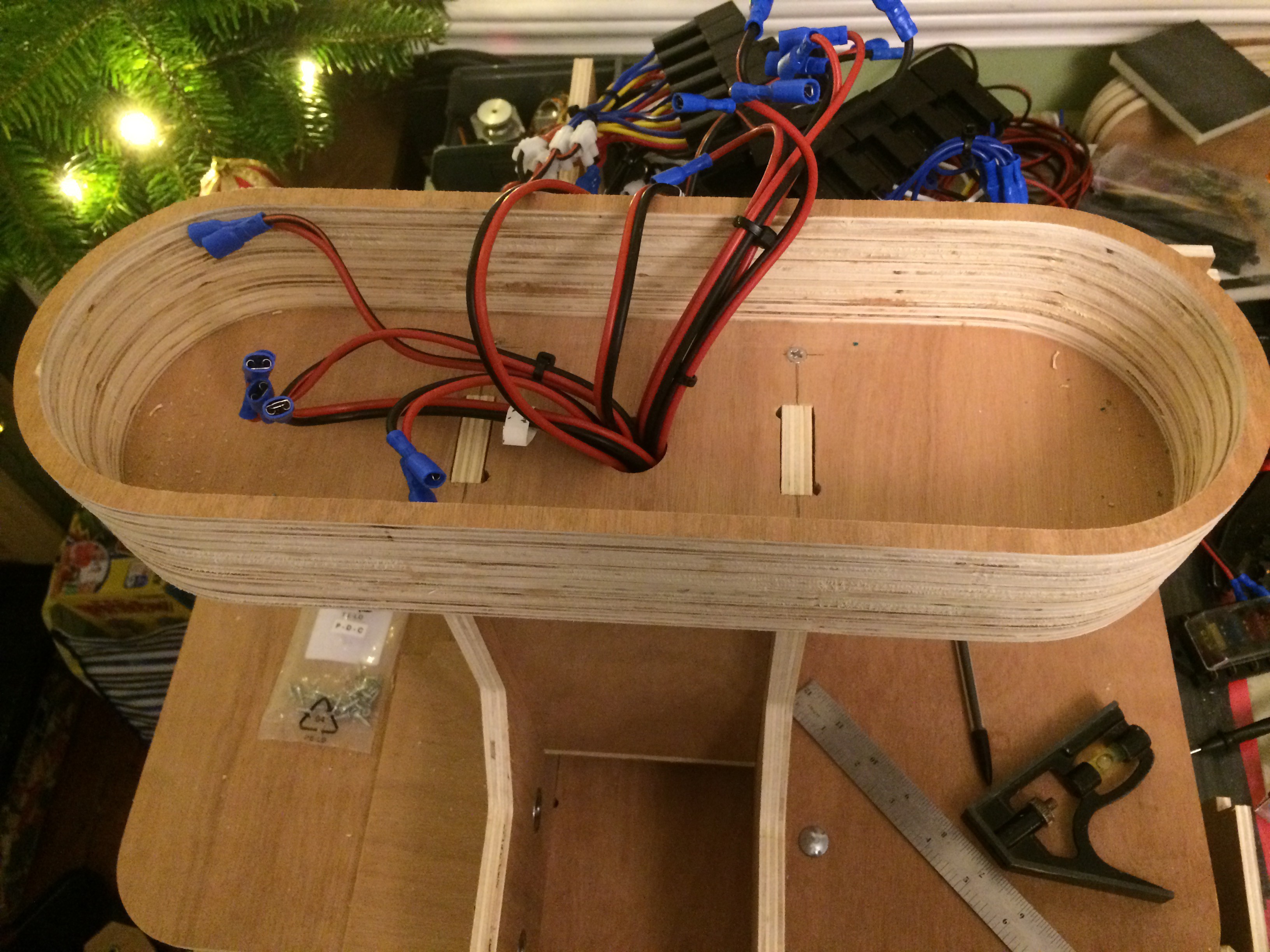
This is the backside of all for joysticks, more on controls later....
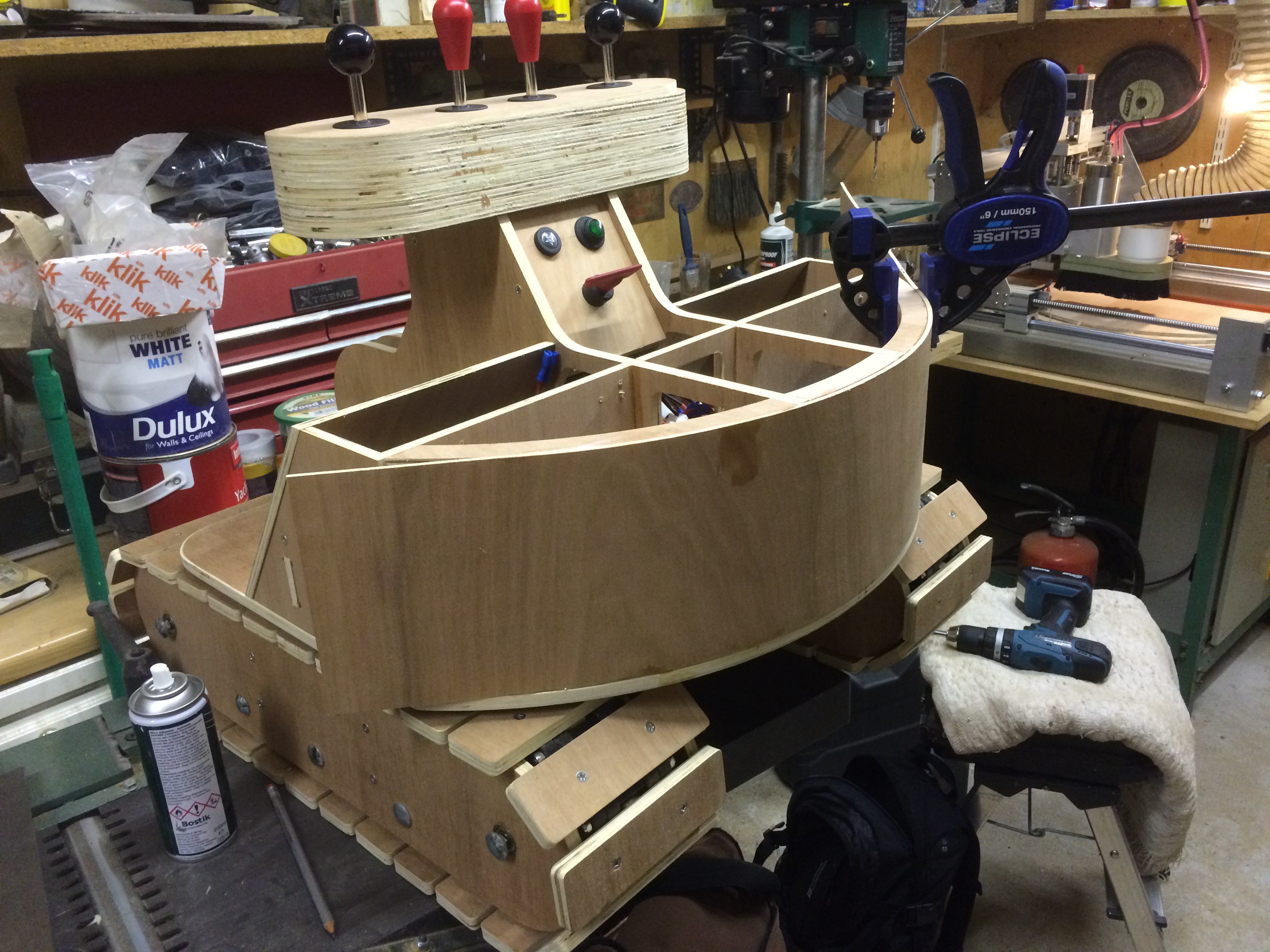
Assembling the counter balance / main body.
Controls - I wanted the controls to operate in the same way as a real excavator so the controls are as follows:

I did have my reservations regarding the complexity of the controls but it didn't take long for my son to work it out.
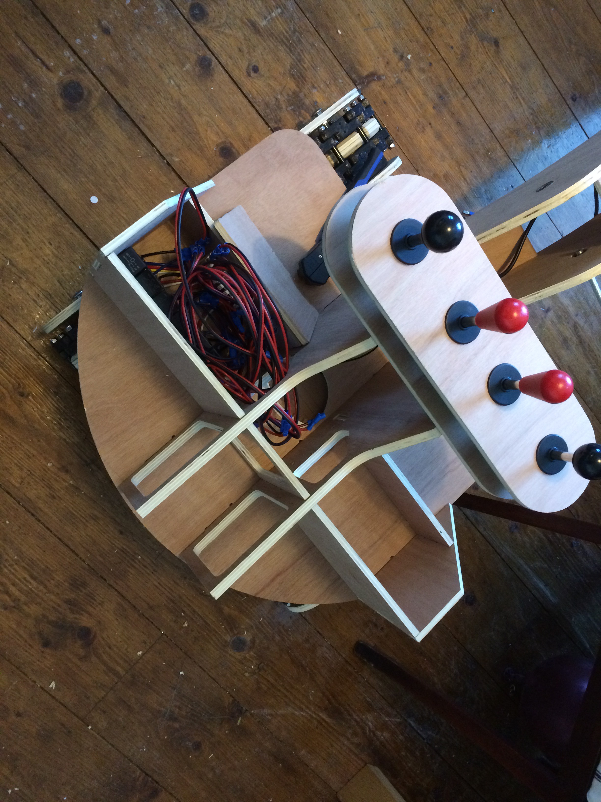
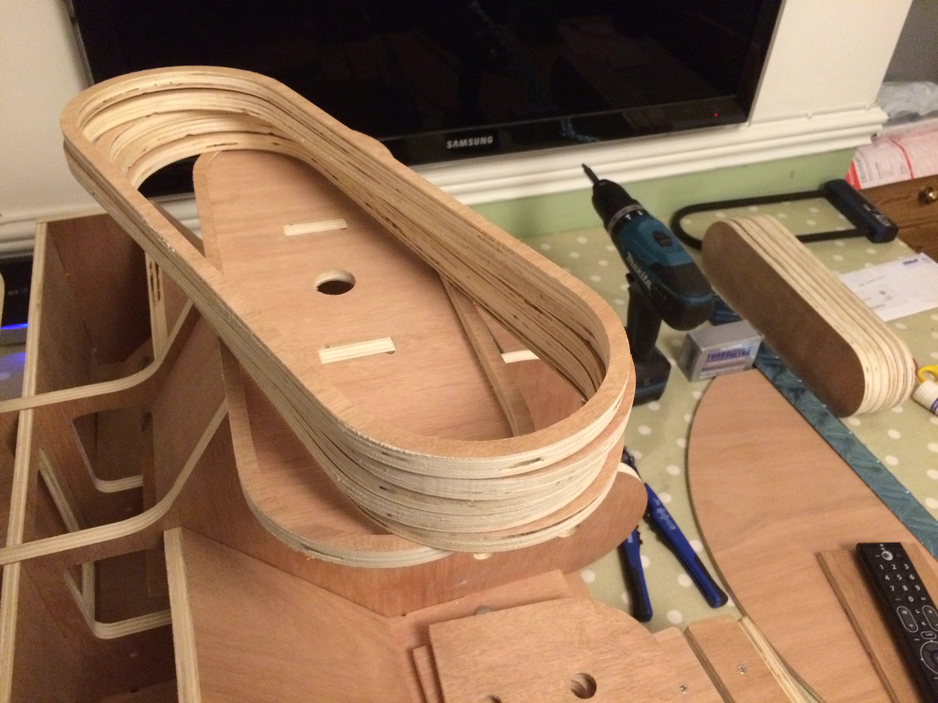
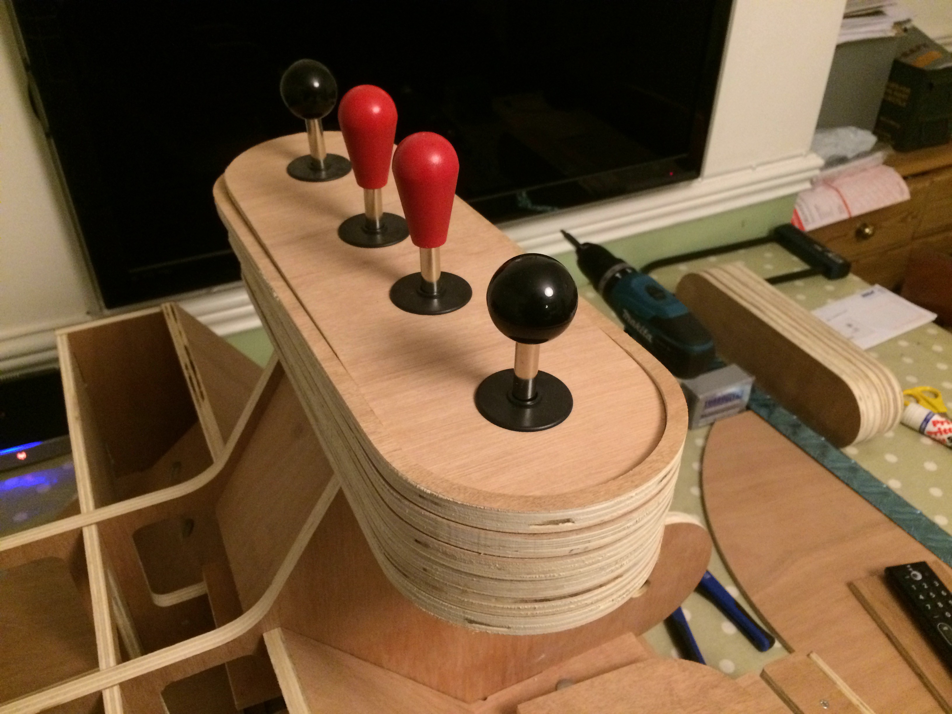
Controls Console - made with pill shaped hoops of ply stacked up to provide a case deep enough to fit the 4 arcade joy sticks. The two sticks in the centre with red tops can only move forwards and backwards in a keyway slot cut to prevent side to side motion of the stick shaft. The two black joy sticks control the slew and the arm.

These are the other controls which include a horn button connected to a piezo buzzer, a button to turn the hazard warning lights on and a key switch for the ignition. The key switch is for a leisure / boat battery isolation.
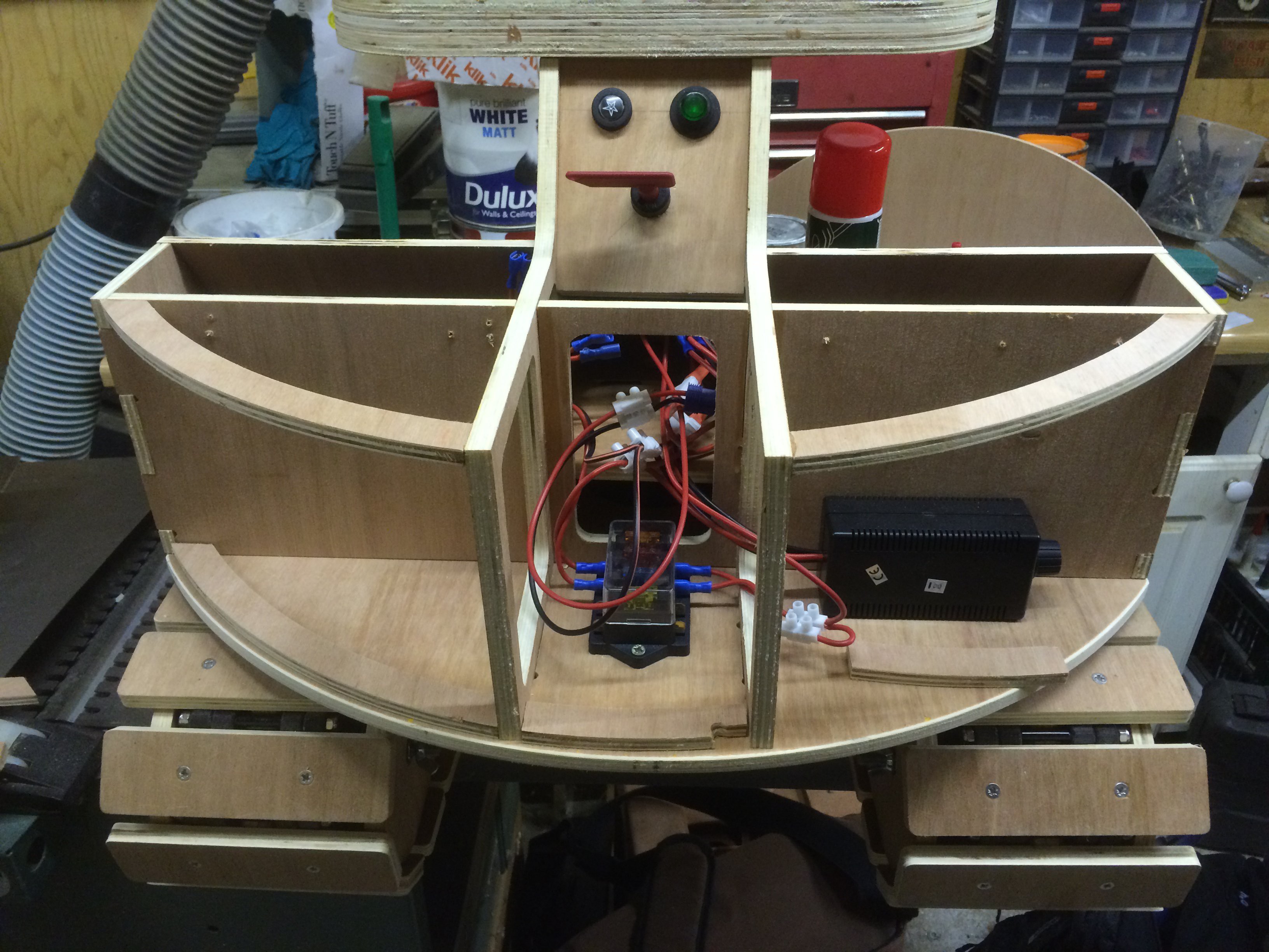
The photo above also shows a fuse box just incase and a speed controller. In the end I used

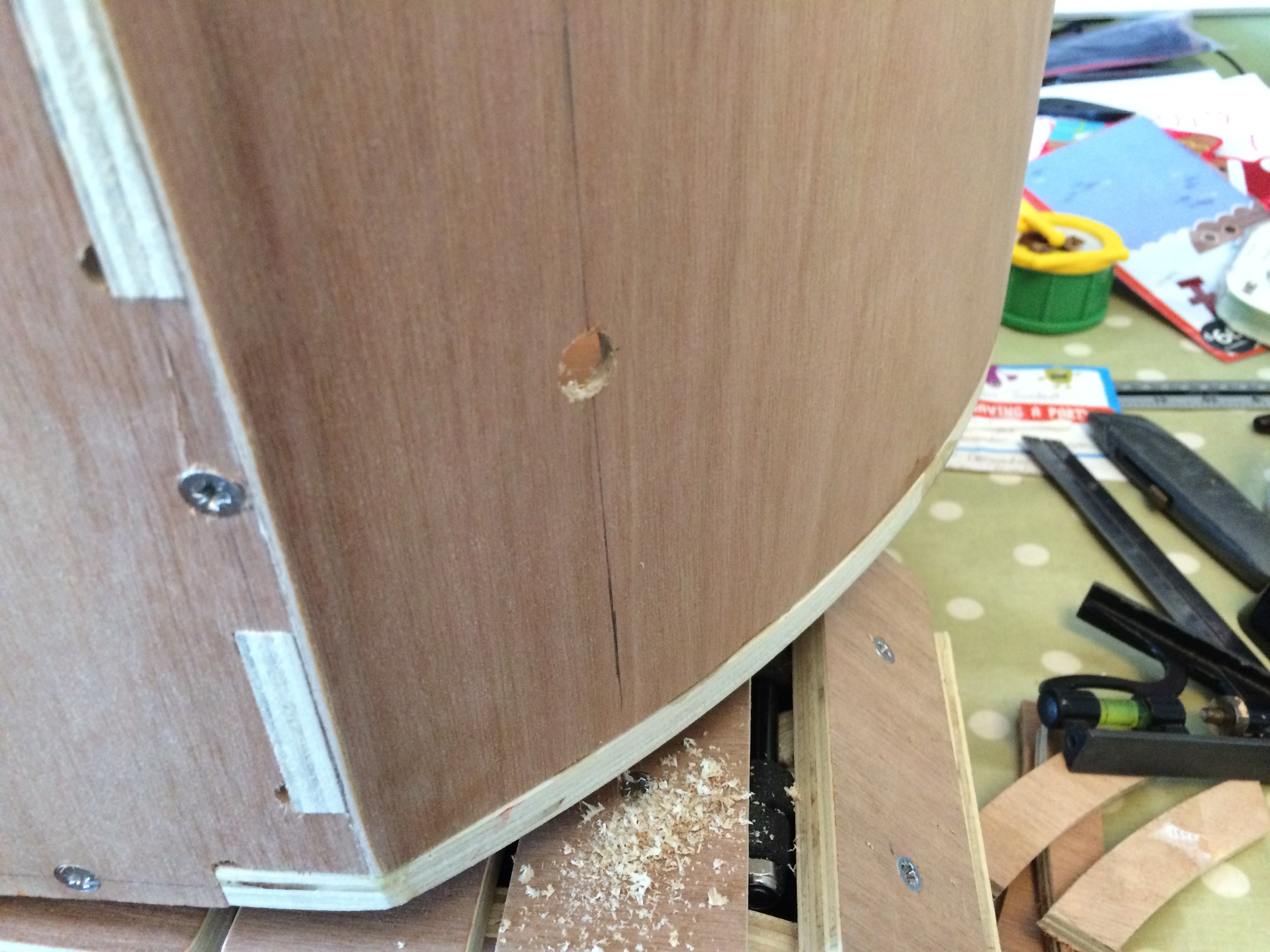
Closing the gap!
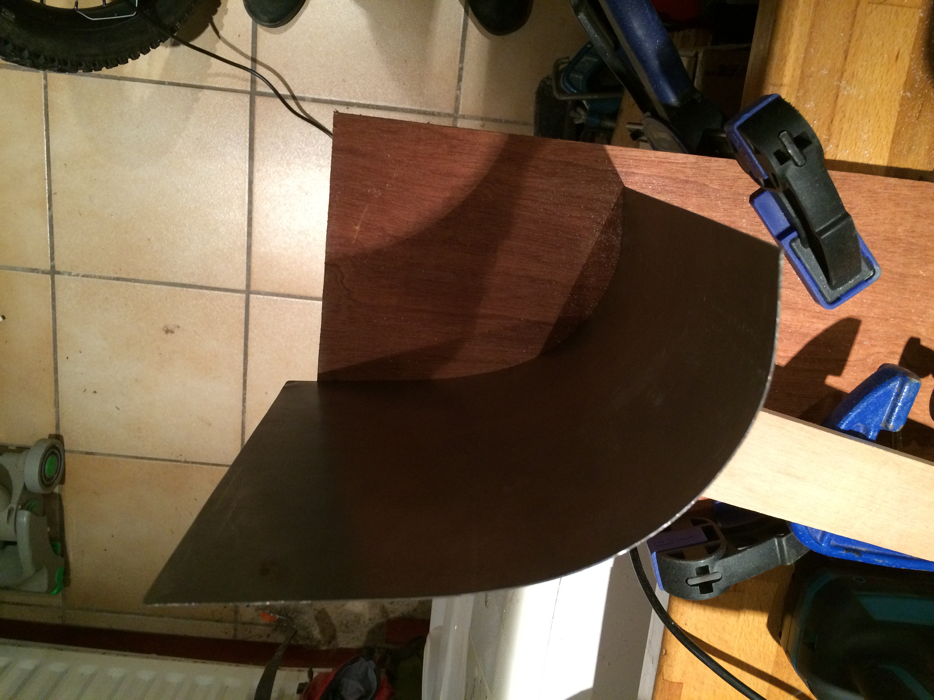
Using clamps and mitre mate to form the curve of the counter weight.
Smooooooth!
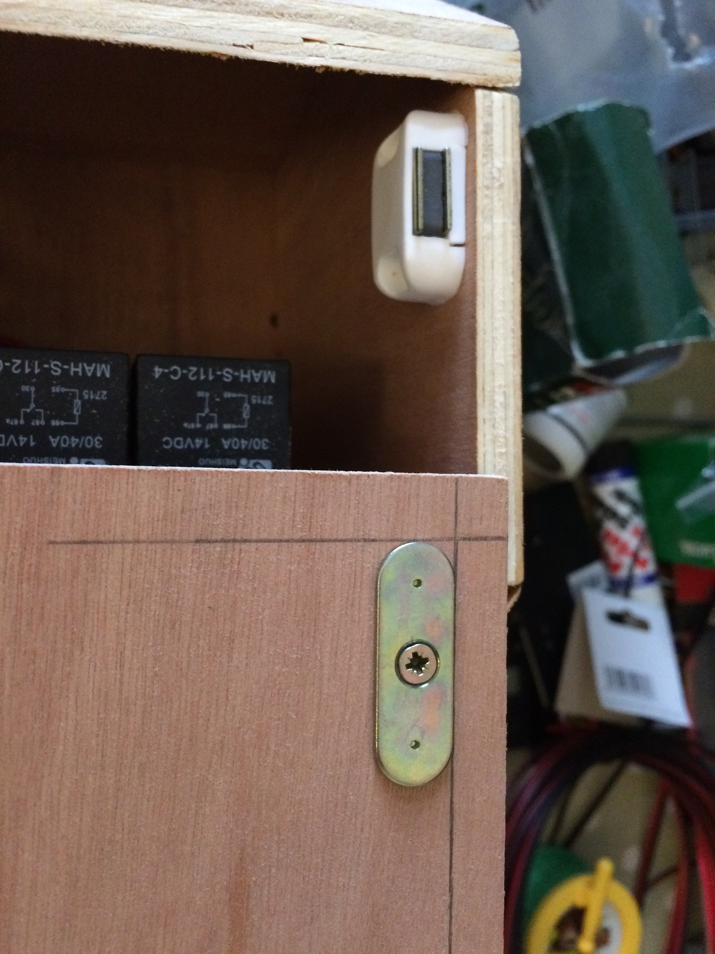
Cabinet magnet for the counter weight lid.
Testing the arm...
1mm steel plate to form the bucket. Used a piece of batten and a steel tube to roll the steel.
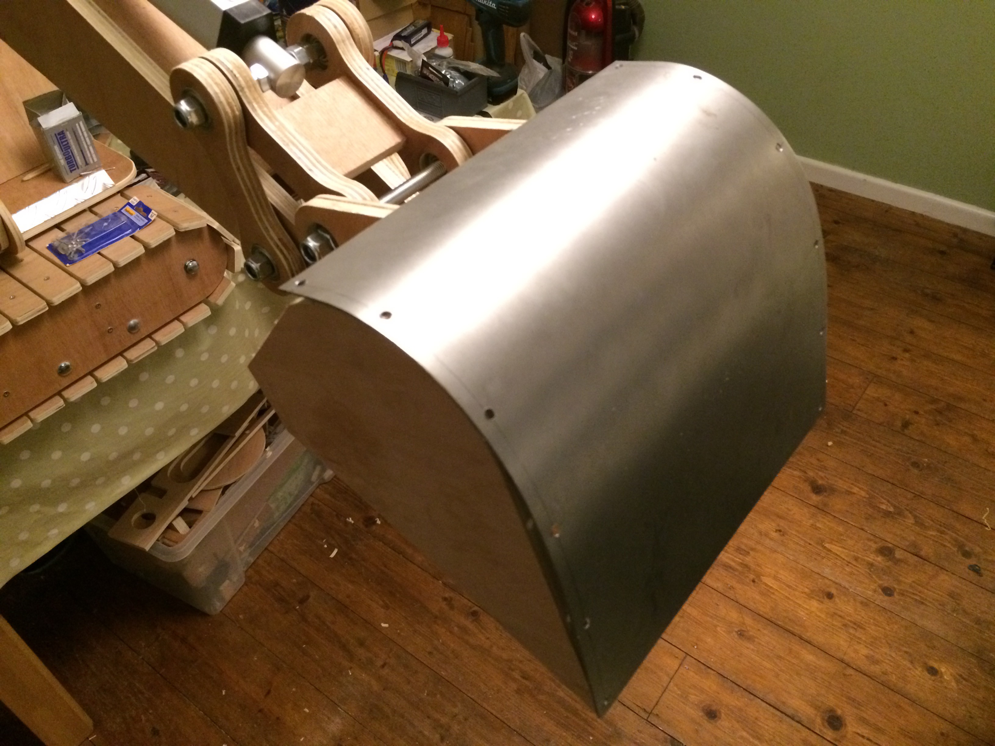
Drilling holes for rivets.
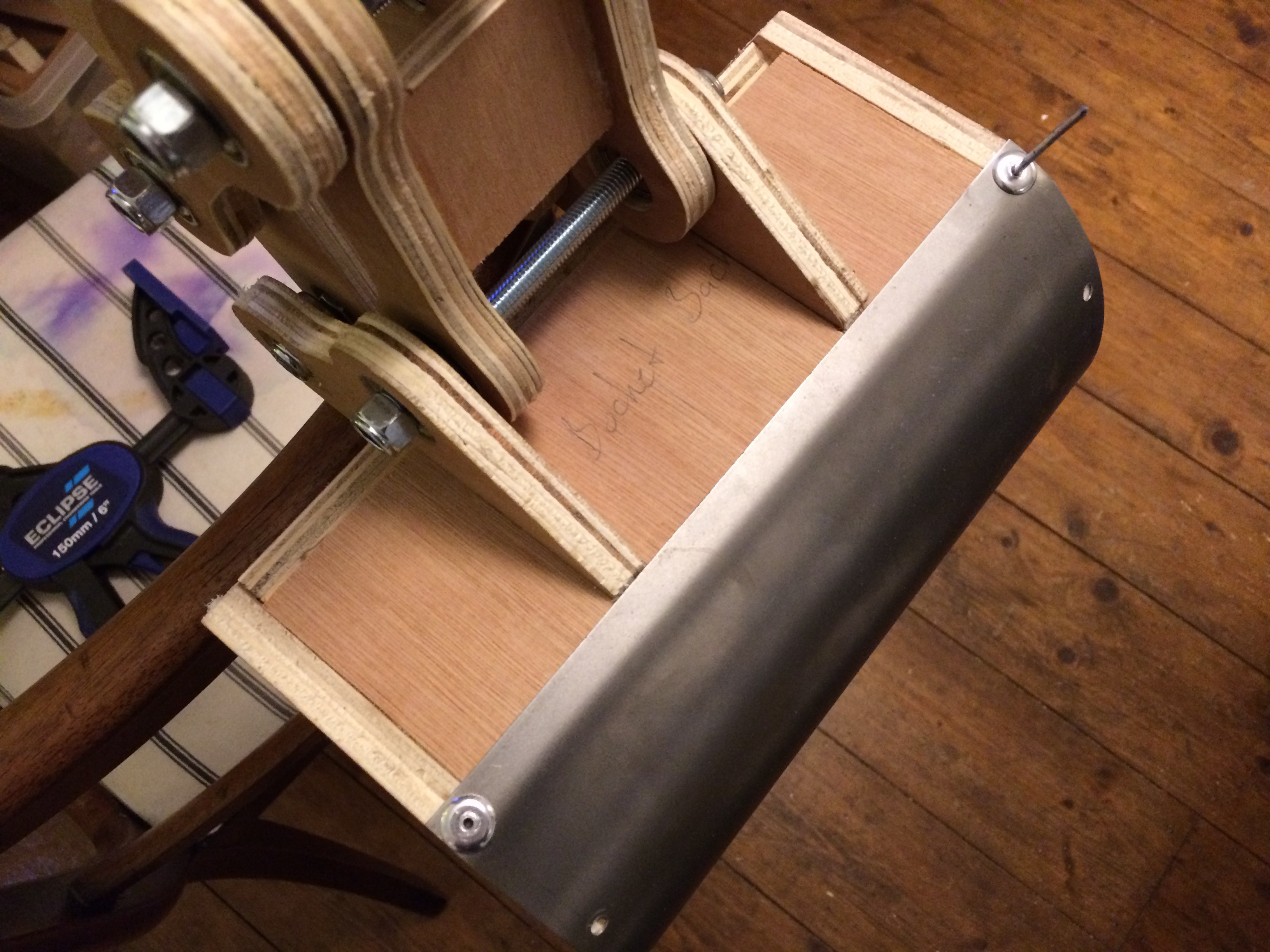
Having a riveting time...

Finished bucket.
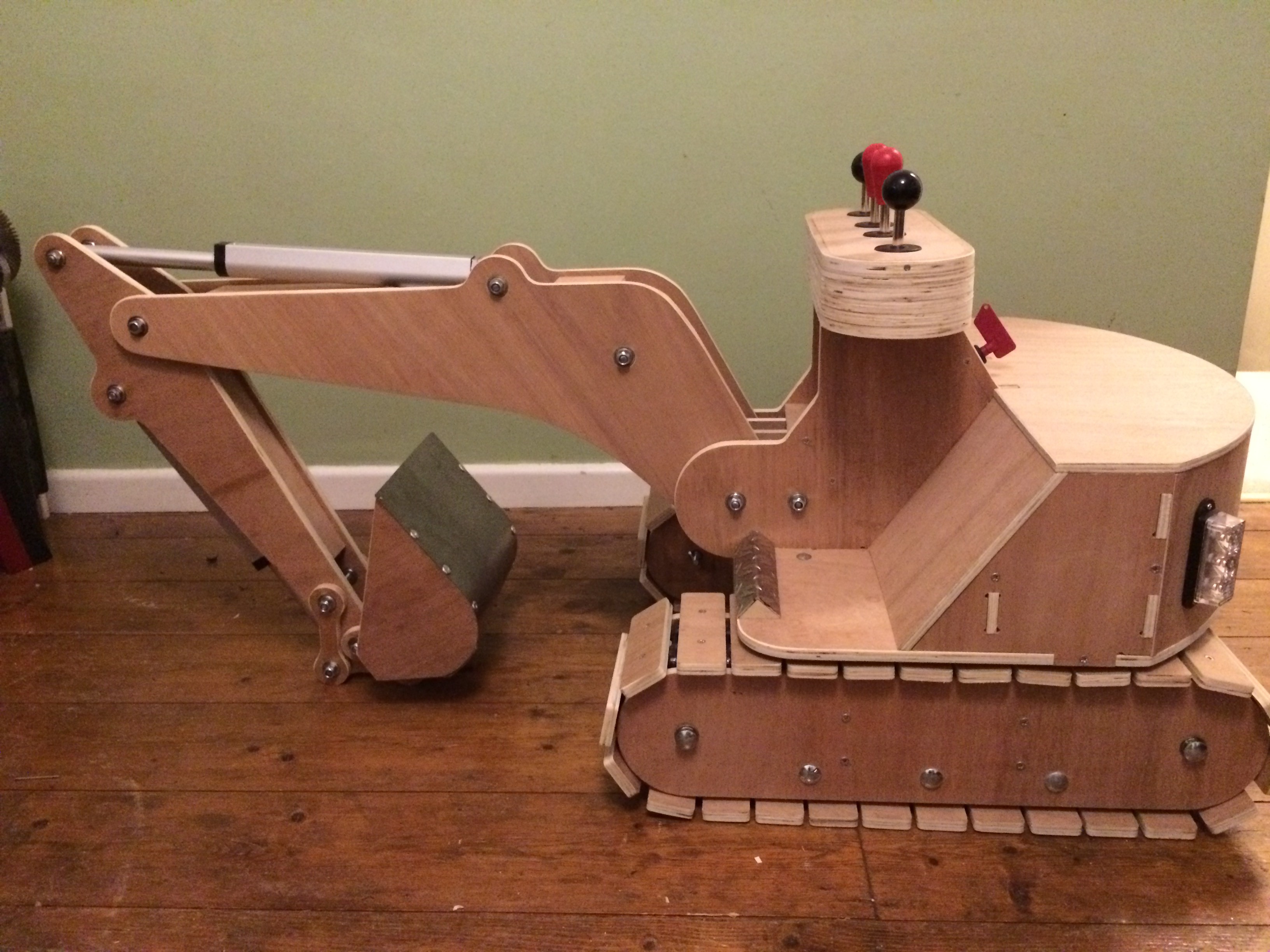
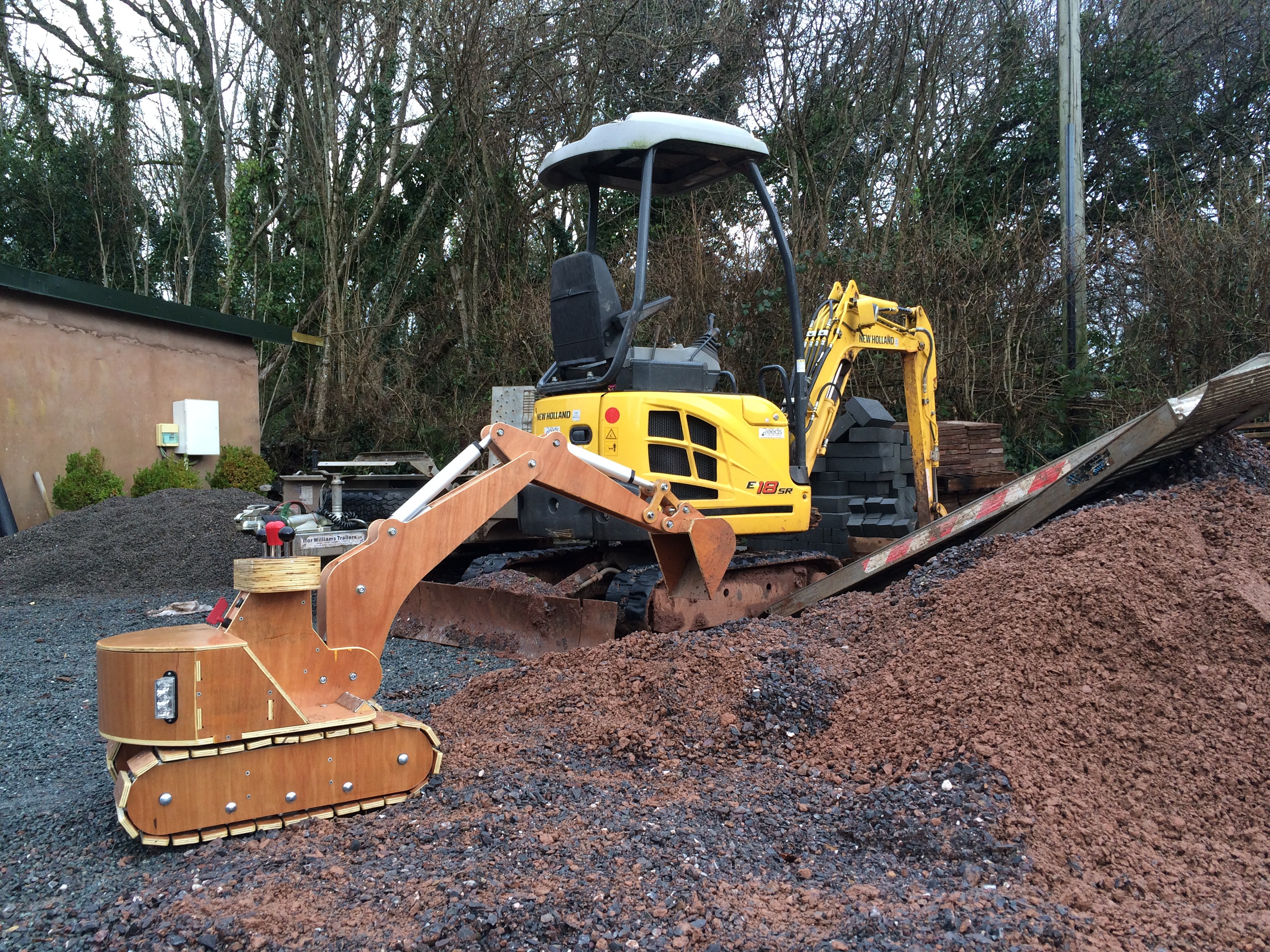
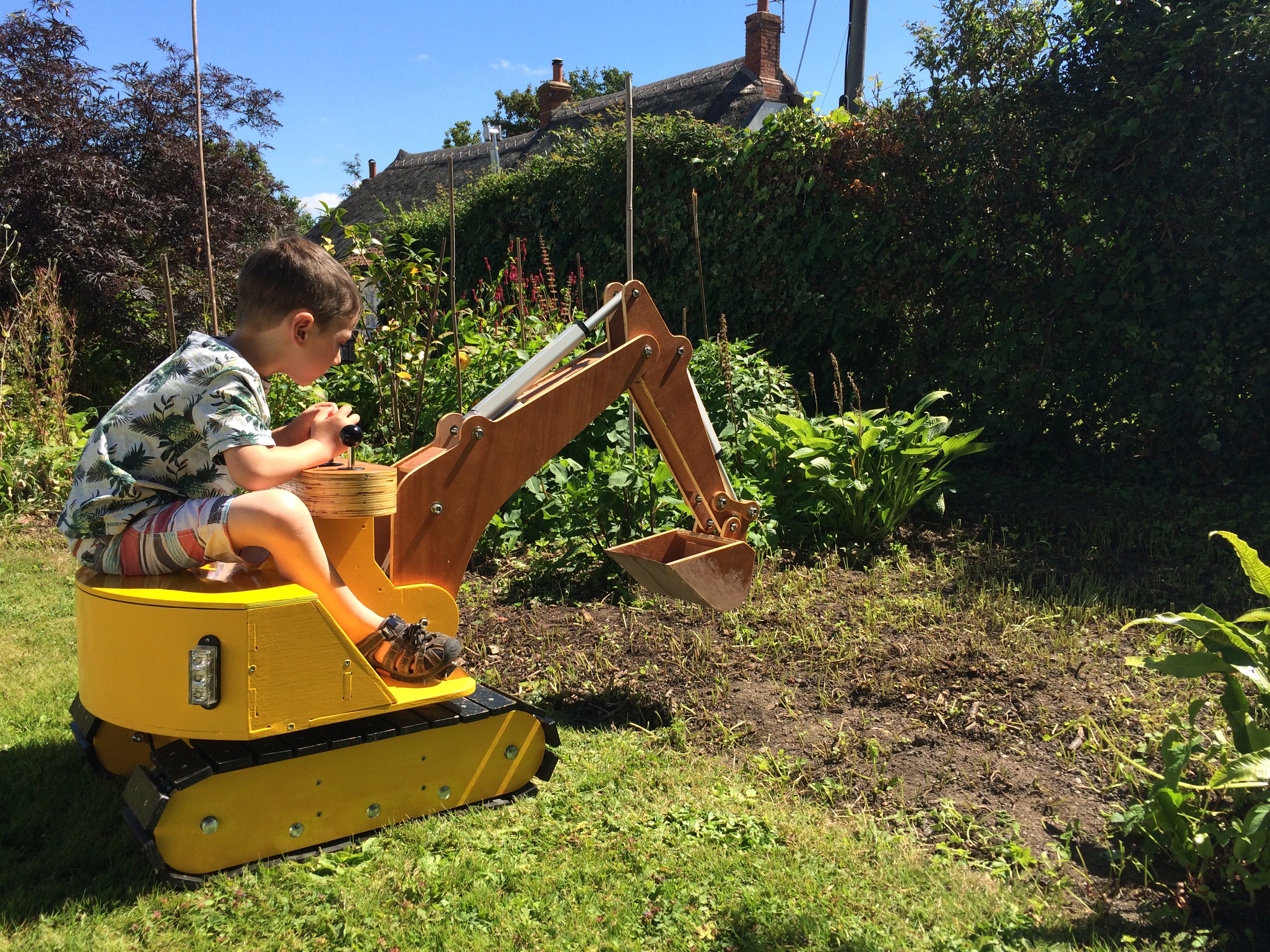
Finished excavator!!!!! Note the foot plates made from checker plate angle in aluminium.
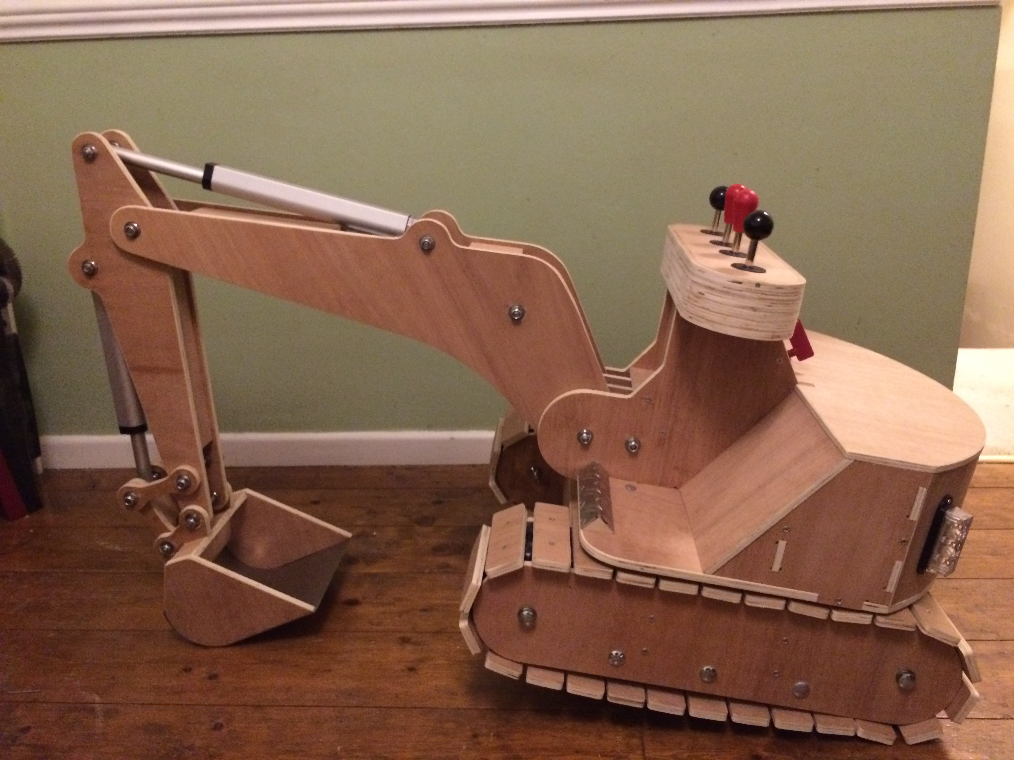
The linear actuators generate so much force that the excavator will lift itself up.
I decided to varnish the excavator then in a moment of madness I later decided to paint it yellow. Im not happy with the yellow and wish i'd kept it natural. I do have plans to make another making various improvements, more on that later.
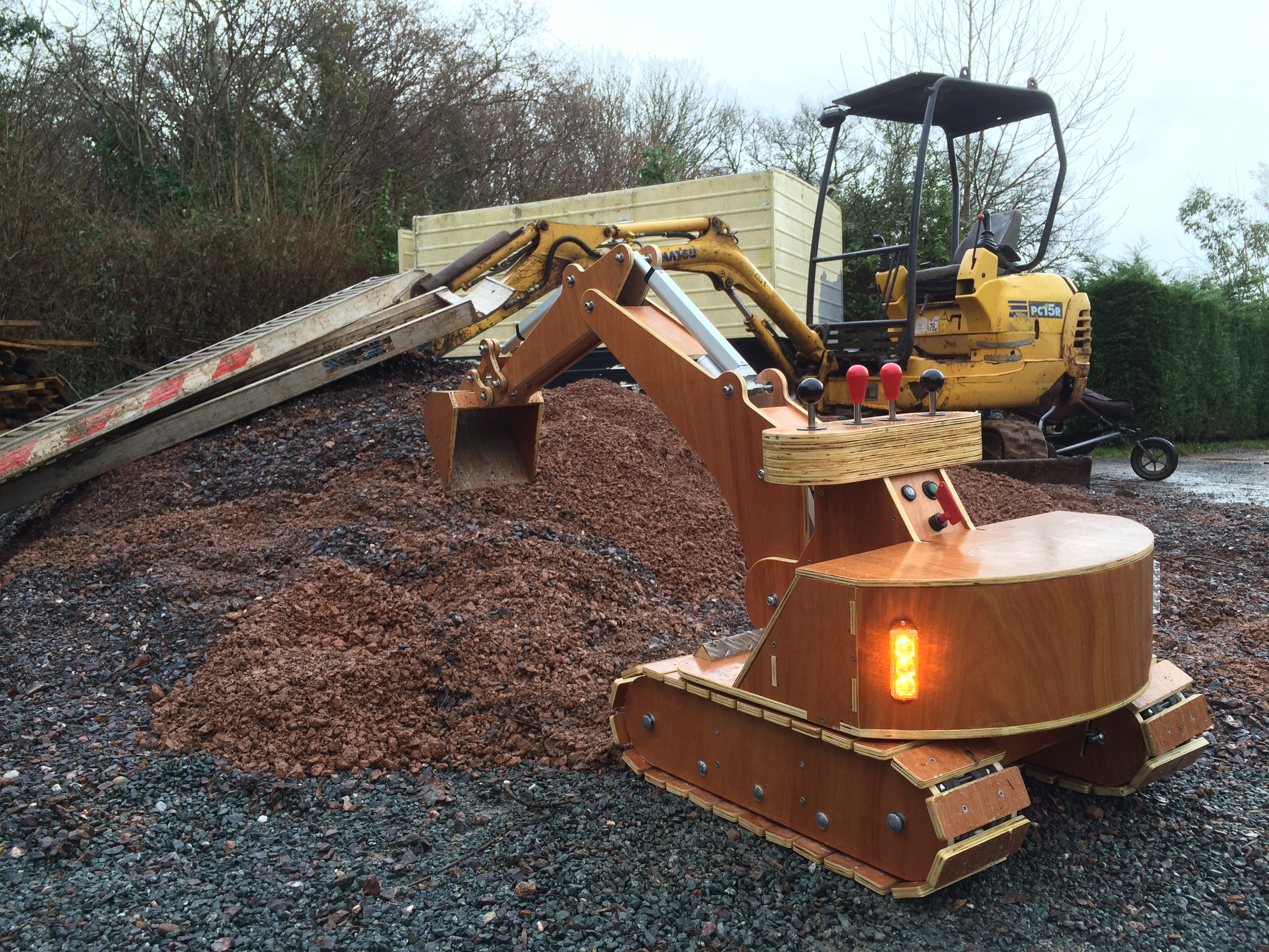
First go in the dirt to iron out the bugs. Caterpillar tracks hate gravel, it was crunch time literally! The whole thing worked amazingly well for a proper first outing. Apart from the slew gear... when the bucket is full the forces on the teeth of the slew where to much for it to handle this resulted in a completely mashed slew annulus and pinion. I decided to two extra stacks of ply to increase the depth of the slew gear and thus spread the load out over a greater surface area. I also added a speed controller to the slew to slow it down.
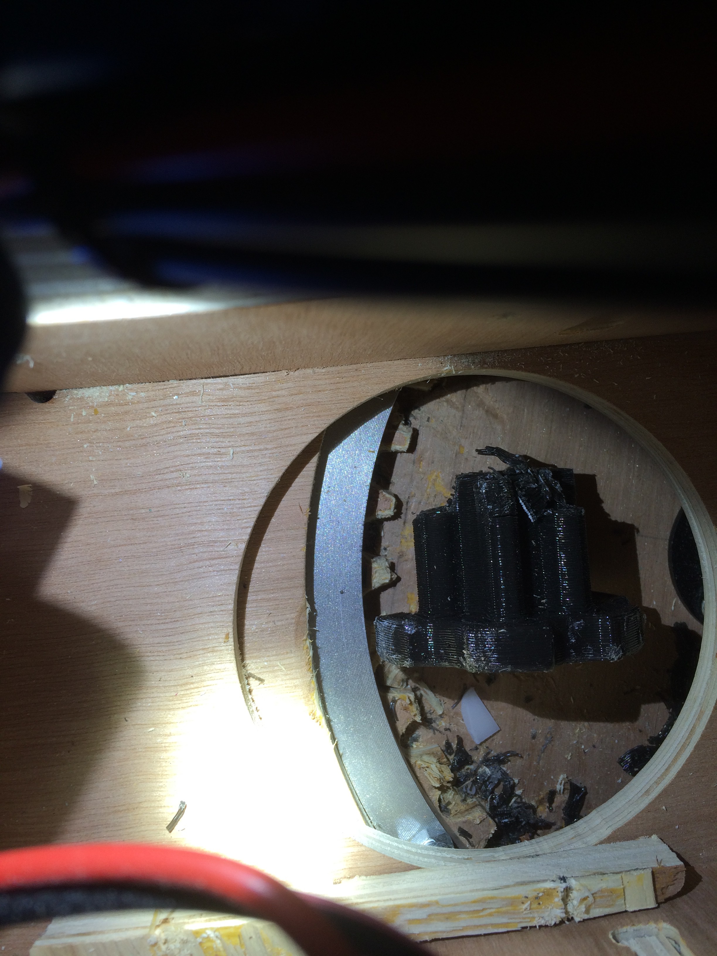
MASHED!
Adding the extra rings to the slew gear annulus. Note the for long bolts that clamp everything together through the entire tracks.
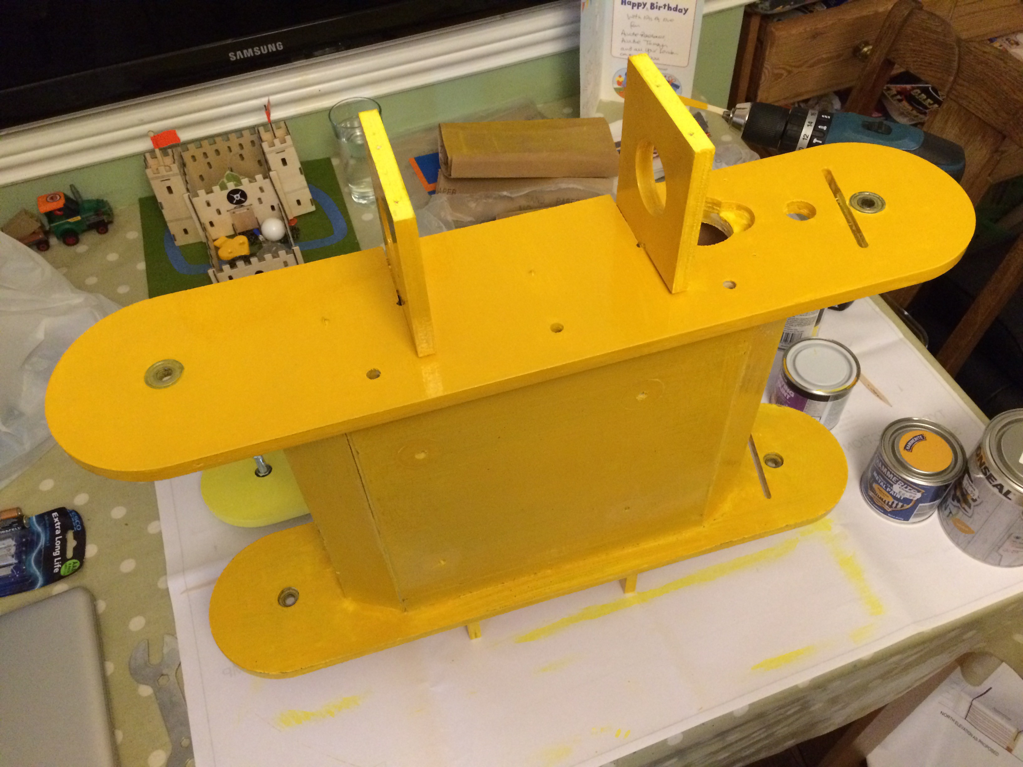
Paint job...
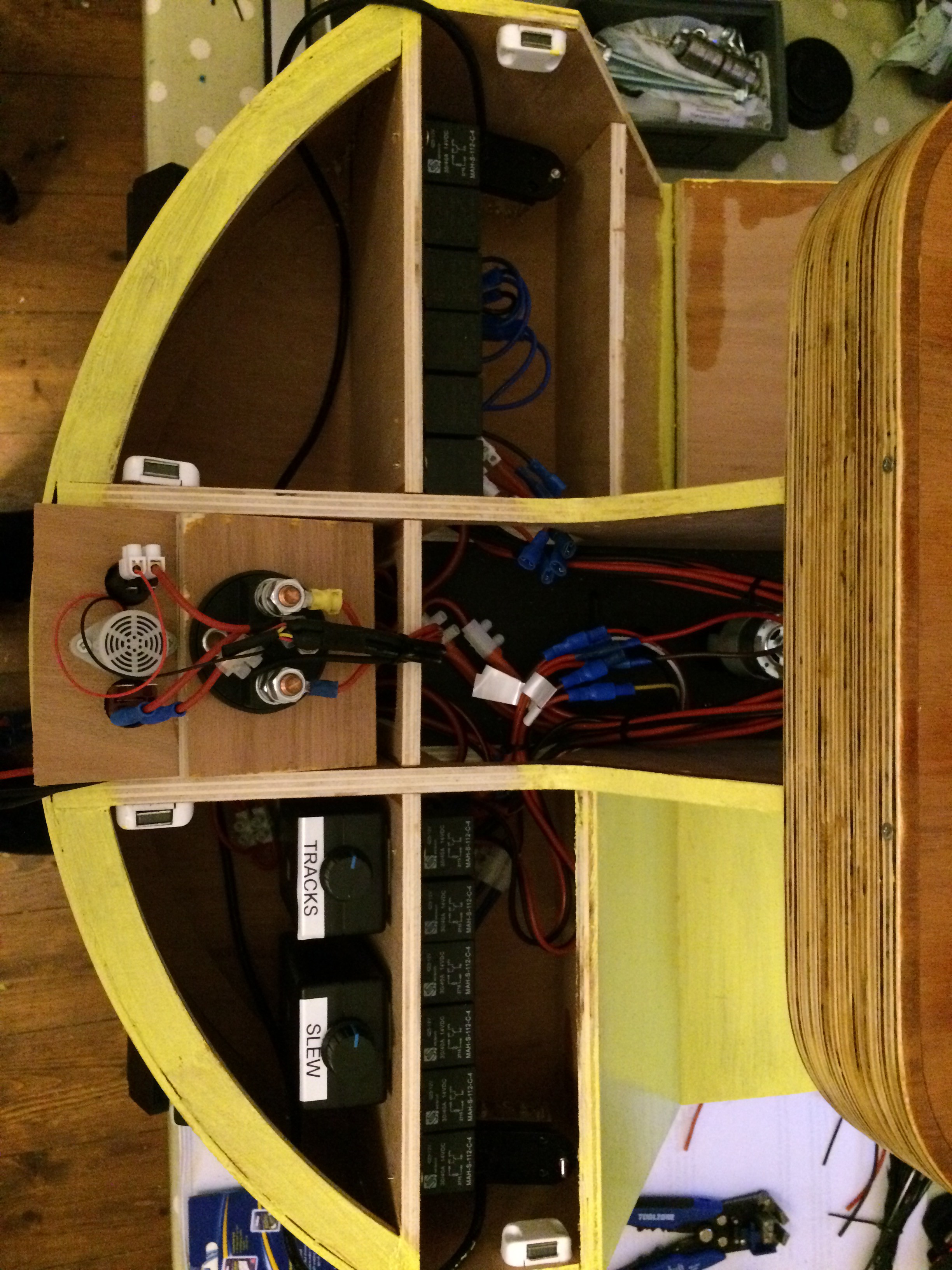
Photo of the speed controllers and wiring to the controls.
Wow you've reached the end!!!
Thanks for looking.....