0%
0%
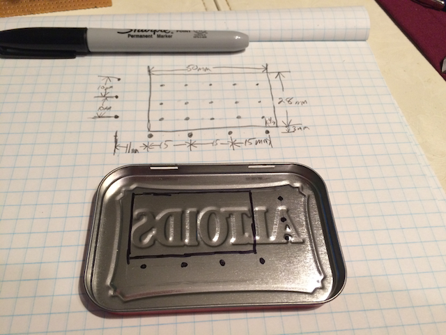
Trinket Timer
A small pocket timer for anything. Reminders, countdowns, etc. Great for kids when you don't want to put a $200 iPod in their hands.
 Korishev
Become a Hackaday.io member
Already have an account? Log in.
Just one more thing
To make the experience fit your profile, pick a username and tell us what interests you.
Pick an awesome username
hackaday.io/
Your profile's URL: hackaday.io/username. Max 25 alphanumeric characters.
Pick a few interests
Projects that share your interests
People that share your interests


 Nicholas Stedman
 Eddie
Eddie

 Enrico
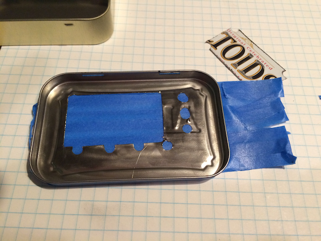
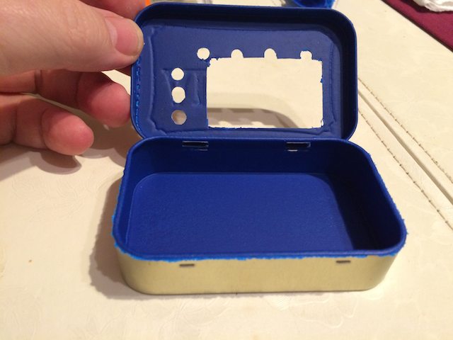
Nice tip on insulating the inside of the Altoids tin... I'm going to use that trick someday.