Close
0%
0%

Word watch

There's not much that's more EDC than a watch. LED matrix-based word watch, inspired by Daniel Rojas's micro word clock recently on the blog

Similar projects worth following
The watch is one of the most common things people carry with them every day, so I think it's a very appropriate entry for the Trinket EDC contest. The only things I can think of that might be more popular are the wallet and the mobile phone, and I don't (yet) have any ideas for adding a Trinket to either of those that I think are worth pursuing right now.

This project aims to develop a watch based on the Adafruit Pro Trinket and an 8×8 LED matrix that is laminated with a letter mask so it can display a few words to indicate the time.

Background

I saw [Daniel Rojas]'s LED matrix-based micro word clock the other day, and thought it was a neat idea. Then I realized I had such an LED matrix, which I'd bought at a local electronics store a few weeks ago for no particular reason. I was originally thinking of using an MSP430 for low power consumption, but there are no MSP430 devkits small enough to mount on one's wrist, so prototyping would be difficult. At this point I realized that because I had to pick a different controller anyway, I might as well enter the Trinket EDC contest.

The layout of the letters will eventually be generated by a genetic algorithm technique, like this. [Alessio] said he couldn't find any grids smaller than 11×11 (for English), but he didn't allow breaks in words like [Daniel] did. Before I get that done, I'll use a version of [Daniel]'s grid, modified to have +1, +2, +3, and +4 indicators for one-minute resolution. With those indicators, this will be the first word clock that I'm aware of to display the time to the minute, not rounded the closest five minutes.

Initial thoughts on design

The Pro Trinket has only 18 GPIO pins, and I need 16 for the LED matrix. This makes pin allocation a bit tight. Furthermore, the Trinket doesn't have 16 GPIOs arranged in two opposite rows of eight. On one side it has seven, and on the other side it has eleven broken into a group of seven and a group of four by the Aref pin in the middle. Furthermore, some of those pins have secondary assignments—UART, I²C, and the built-in LED. I will have to figure out how to connect the LED matrix to avoid conflicts. I'm planning to use the built-in LED as a low-battery indicator, so I don't want it lighting up as the matrix is scanned. If I end up soldering the matrix directly to the Trinket, I'll insulate or shorten the pins I don't want connected, and wire them elsewhere.

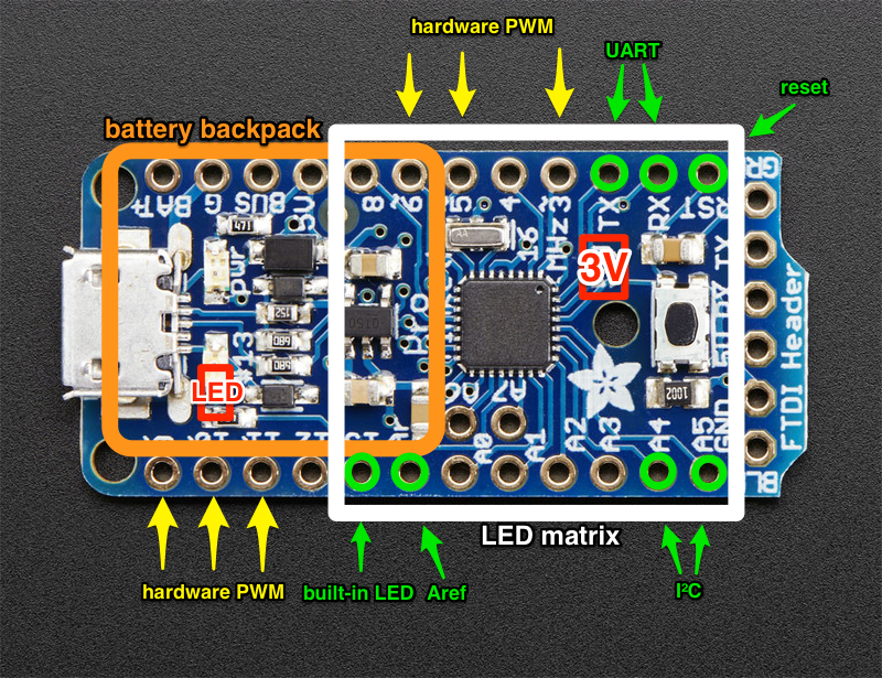
(Note that I made this diagram based on the 5 V Pro Trinket, and Skitch won't let me replace the base image without having to redo all of the annotations, so I've corrected the differences that matter in red: the voltage label and the exact location of the pin 13 LED.)

Expect a project log in the coming days with tentative solutions to these problems, as well as a 3D mockup of the assembly (hopefully).

However, I expect the electrical design to be one of the easier aspects of this project. I expect miniaturization and generating the word clock grid will be quite a bit harder.

Also, in the interest of miniaturization, I don't plan to include a real-time clock chip. Instead, I will use the Trinket's AVR to keep time. Based on its datasheet [PDF] (see Fig. 31-333, p. 493 and Fig. 31-338, p. 495), I'm estimating it will consume an average current of ~2 mA, which will result in ~75-hour battery life using a 150 mAh battery. Time will be set via UART initially, and by the gesture sensor later.

View all 9 components

  • Parts arriving!

    PointyOintment12/24/2014 at 00:48 0 comments

    I placed one order with Adafruit and one with SparkFun last Tuesday, for parts for all three of my Trinket EDC Contest entries. Unfortunately, SparkFun wasn't offering USPS Priority Mail Express International for some reason, so I had to shift stuff around so all of the things I needed right away were in the Adafruit order, for which I could use the fast shipping. It arrived at the post office this morning; I'm going to go pick it up tomorrow. Here are the relevant parts I ordered:

    Yes, that Teensy is relevant. :D

    With the parts arrived/shipped, all three projects will be going ahead even if they miss the contest deadline.

    Also, as I said in a comment, the MAX7219CNG is just in case I can't get it working without, because it would make the watch way bulkier.

  • A minor setback

    PointyOintment12/09/2014 at 00:46 0 comments

    Two days ago I uploaded an image of a 3D model I'd made of the Pro Trinket. I was going to do the same for the other components, but my computer stopped working. It does this thing whenever it restarts where its screen doesn't work for about 40 minutes after booting. This time, though, it didn't work for a couple of days. I tried restarting again, resetting the SMC, etc., and the best I got was the screen working for a few seconds after boot and then going black. I remembered that the last time this happened, I had to boot the computer and then leave it closed for several hours to get it to work again. I did so, and it works again. I will try to model the other components later tonight.


  • Displaying raster images

    PointyOintment12/03/2014 at 07:08 0 comments

    After much struggling, I managed to get it displaying hardcoded raster images chosen by sending a letter over the serial connection. Here it is displaying A, B, C, a smiley face, and the LEDs that are illuminated in my mockup image (taken from [Daniel]'s photo):

    direct video link in case the embed doesn't work for you (YT: LED matrix: predefined raster images (0:20))

    I first tried to use a switch case statement to load the chosen pixel array into the pixel array that refreshScreen() reads from, but apparently you can't set all elements of an array unless you're doing so when you're first defining it. Seems strange to me, but whatever. I changed those pixel arrays to constants, and then made a switch case statement inside refreshScreen() that chooses among them as it draws to the LED matrix. After that I had loads of syntax errors resulting from moving code around and trying different approaches, but they were all easily fixed. It's not particularly efficient (or maintainable), but it looks like it updates plenty fast—much faster than the x-y demo I did earlier, for some reason. It's good enough for a proof of concept, at least. The actual word clock function will use a more dynamic way of generating the pixel arrays. Here's the code:

    char imageID;
    
    // images:
    const int pixelsA[8][8] = {
       {1,1,1,0,0,1,1,1},
       {1,1,0,0,0,0,1,1},
       {1,0,0,1,1,0,0,1},
       {1,0,0,1,1,0,0,1},
       {1,0,0,0,0,0,0,1},
       {1,0,0,1,1,0,0,1},
       {1,0,0,1,1,0,0,1},
       {1,0,0,1,1,0,0,1}
    };
    const int pixelsB[8][8] = {
       {1,0,0,0,0,0,1,1},
       {1,0,0,1,1,0,0,1},
       {1,0,0,1,1,0,0,1},
       {1,0,0,0,0,0,1,1},
       {1,0,0,0,0,0,1,1},
       {1,0,0,1,1,0,0,1},
       {1,0,0,1,1,0,0,1},
       {1,0,0,0,0,0,1,1}
    };
    const int pixelsC[8][8] = {
       {1,1,0,0,0,0,1,1},
       {1,0,0,0,0,0,0,1},
       {0,0,1,1,1,1,0,0},
       {0,1,1,1,1,1,1,1},
       {0,1,1,1,1,1,1,1},
       {0,0,1,1,1,1,0,0},
       {1,0,0,0,0,0,0,1},
       {1,1,0,0,0,0,1,1}
    };
    const int pixelsSmile[8][8] = {
       {0,0,1,1,1,1,0,0},
       {0,1,1,1,1,1,1,0},
       {1,1,0,1,1,0,1,1},
       {1,1,1,1,1,1,1,1},
       {1,0,1,1,1,1,0,1},
       {1,1,0,0,0,0,1,1},
       {0,1,1,1,1,1,1,0},
       {0,0,1,1,1,1,0,0}
    };
    const int pixelsWords[8][8] = {
       {1,1,0,0,0,0,0,0},
       {0,0,1,0,1,0,1,1},
       {1,1,1,0,0,0,0,1},
       {1,1,1,1,1,1,1,1},
       {1,1,1,1,1,1,1,1},
       {1,1,0,0,0,0,0,0},
       {1,1,1,1,1,1,1,1},
       {1,1,1,1,1,1,1,1}
    };
    
    void readSerial() {
       // get value from serial:
       imageID = Serial.read();
    }
    
    void refreshScreen() {
       // iterate over the rows (anodes):
       for (int thisRow = 0; thisRow < 8; thisRow++) {
          // take the row pin (anode) high:
          digitalWrite(row[thisRow], HIGH);
          // iterate over the cols (cathodes):
          for (int thisCol = 0; thisCol < 8; thisCol++) {
             // get the state of the current pixel:
             //int thisPixel = pixels[thisRow][thisCol];
             int thisPixel;
             switch (imageID) {
                case 'a':
                   thisPixel = pixelsA[thisRow][thisCol];
                break;
                case 'b':
                   thisPixel = pixelsB[thisRow][thisCol];
                break;
                case 'c':
                   thisPixel = pixelsC[thisRow][thisCol];
                break;
                case 's':
                   thisPixel = pixelsSmile[thisRow][thisCol];
                break;
                case 'w':
                   thisPixel = pixelsWords[thisRow][thisCol];
                break;
             }
             // when the row is HIGH and the col is LOW,
             // the LED where they meet turns on:
             digitalWrite(col[thisCol], thisPixel);
             // turn the pixel off:
             if (thisPixel == LOW) {
                digitalWrite(col[thisCol], HIGH);
             }
          }
          // take the row pin low to turn off the whole row:
          digitalWrite(row[thisRow], LOW);
       }
    }

  • Basic LED matrix control

    PointyOintment12/03/2014 at 04:37 0 comments

    Modifying the Arduino example I linked to earlier, I made a basic sketch that takes X and Y positions via serial and illuminates the corresponding LED.

    Here's the code I added/changed:

    void loop() {
       // read input:
       while (Serial.available() > 0) {
       readSerial();
       }
    
       // draw the screen:
       refreshScreen();
    }
    
    void readSerial() {
       // turn off the last position:
       pixels[x][y] = HIGH;
       // get value from serial:
       x = Serial.parseInt();
       y = Serial.parseInt();
       if (Serial.read() == '/n') {
          x = constrain(x, 0, 7);
          y = constrain(y, 0, 7);
       }
       // set new pixel position on:
       pixels[x][y] = LOW;
    }

    Now I can just type two digits from 0 to 7, separated by a non-digit (e.g. a space) in the serial terminal, and the corresponding LED on the matrix will light up.

    Next I will try to get it to display predefined raster graphics. This will be the basis of the word clock functionality.

  • The LED matrix

    PointyOintment12/02/2014 at 06:50 0 comments

    I picked up this LED matrix at a local electronics store several weeks ago, thinking I might find an interesting project for it:

    (Is that green bag supposed to be static-dissipative?)

    The pinout of these is very strange. I found this Arduino tutorial quite helpful. I tested it on a breadboard:

    It looks like it should work fine.


    echo "…" | wc
    11 58 340

    yay

View all 5 project logs

Enjoy this project?

Share

Discussions

Mike Szczys wrote 01/05/2015 at 22:05 point

It'll be fun to see this thing strapped to your wrist. As far as the AVR keeping time, I think you can measure the system clock by toggling a pin and then account for deviation based on that measurement to get better accuracy.

Also, as a future challenge you could try adding an external 32.768 kHz clock crystal (I'm pretty sure the 328 supports that option) just to drive the internal RTC measurements.

  Are you sure? yes | no

PointyOintment wrote 01/08/2015 at 23:12 point

Hi Mike. Thanks for the comment. Calibrating the clock frequency is a good idea; I actually hadn't thought of that. I'll keep that in mind. And when I have the datasheet handy I'll try to figure out how to use a 32.768 kHz crystal. I hope it can drive the timers while the chip is asleep—I was planning to keep track of time by using a timer interrupt to wake up and increment a variable, rather than staying awake all the time just to run a soft RTC.

  Are you sure? yes | no

Scissorfeind wrote 12/10/2014 at 06:04 point
Awesome job coding that up, I'm about to have my own go at something similar. I noticed you aren't using any external components to control your display?

  Are you sure? yes | no

PointyOintment wrote 12/11/2014 at 00:35 point
That's the plan. I thought external components would make it too bulky—I already have to squeeze in the battery backpack and the gesture sensor breakout board, and I have plans to put a USB-to-serial bridge chip somewhere in the middle under the display to enable time setting over USB. I'm probably going to order a MAX7219CNG (https://www.sparkfun.com/products/9622 ) just in case I can't get it working, but I think I'll be able to. That one chip is about as long as the whole Trinket. According to my current plan 16 of the Trinket's 18 GPIOs will go to the LED matrix, one (pin 13) will be used only for the built-in LED, two will go to I2C for the gesture sensor, one will be an interrupt line for the gesture sensor, one will be an ADC input for battery voltage, and one will be an input for a button (maybe shared with the gesture sensor interrupt), and possibly more I'm forgetting right now. That leaves me with a negative number of pins free, which I'm actually happy about because it's an extra challenge to make the pins do double duty. I will probably cut the two going to the USB port (because they serve no purpose for me), which gives two more GPIO lines, and there are two ADC input-only pins that I can use for the light sensor and battery voltage, but I'm not sure that even with those extra pins I'd have enough for each pin to have only one purpose.

I'm starting planning/ordering for another two projects that will use LED displays right now, and I'm going to use driver chips for those. One will be a 4-digit 14-segment display driven by two 595s and the Trinket on the common cathodes, and the other will be a 12-digit 7-segment display sharing an SX1509 (https://www.sparkfun.com/products/11502 ) with a keypad.

  Are you sure? yes | no

PointyOintment wrote 12/11/2014 at 01:16 point
Also, the 12-digit display works out to 20 pins (12 digit cathodes + 8 segment anodes incl. decimal point), so I have to either do something funny with the connections to the SX1509 or use another chip. I think the SX1509 on the cathodes and a 595 on the anodes would work well, and then the SX1509 wouldn't be impeded in its keypad scanning at all.

  Are you sure? yes | no

Similar Projects

Does this project spark your interest?

Become a member to follow this project and never miss any updates