Close
0%
0%

Wind Measurement

A simple pocket tool to measure and log wind speed and direction.

Similar projects worth following
A simple pocket tool to measure and log wind speed and direction. An entry for the trinket pro contest.

Theory of operation.

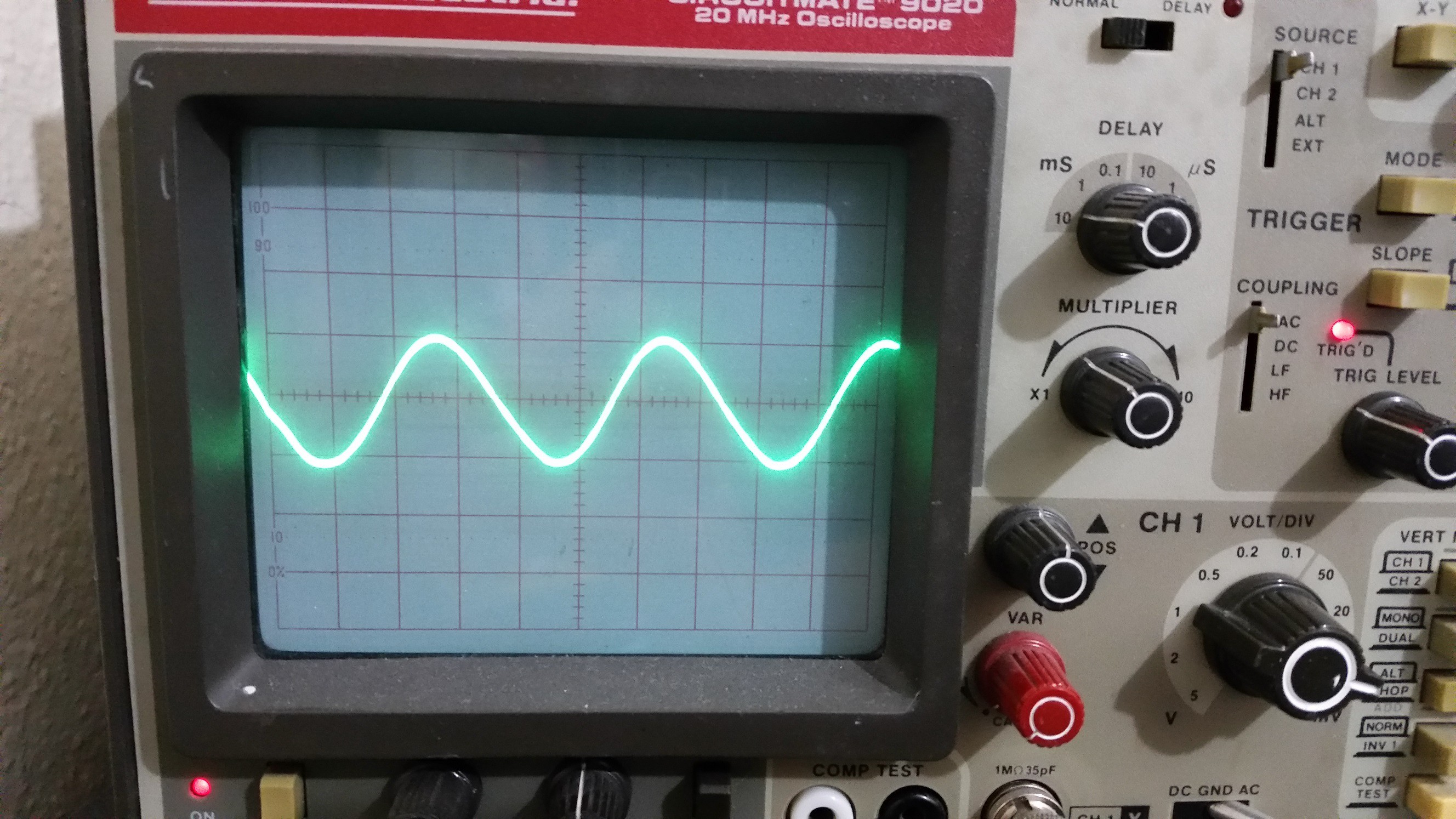
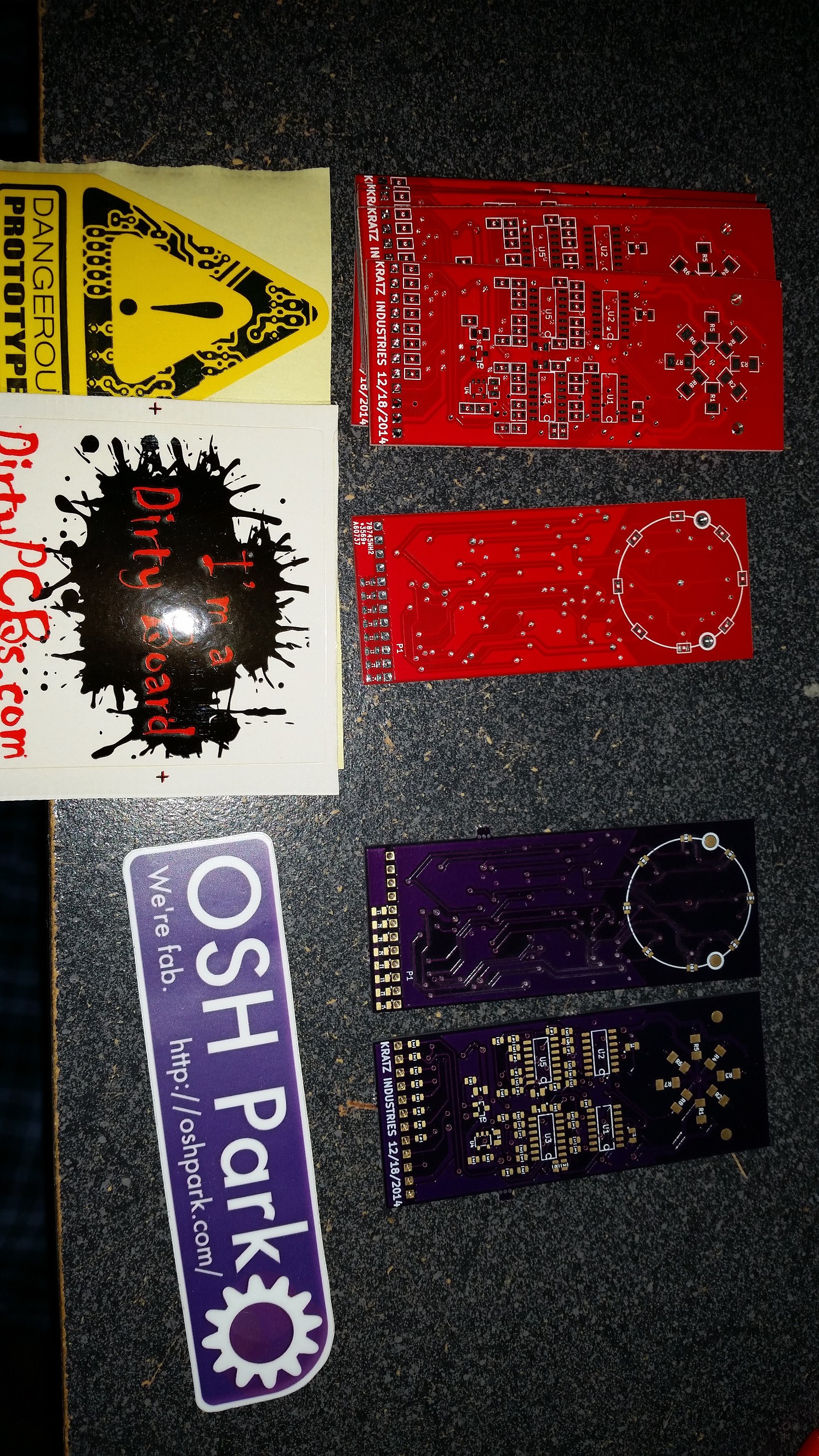
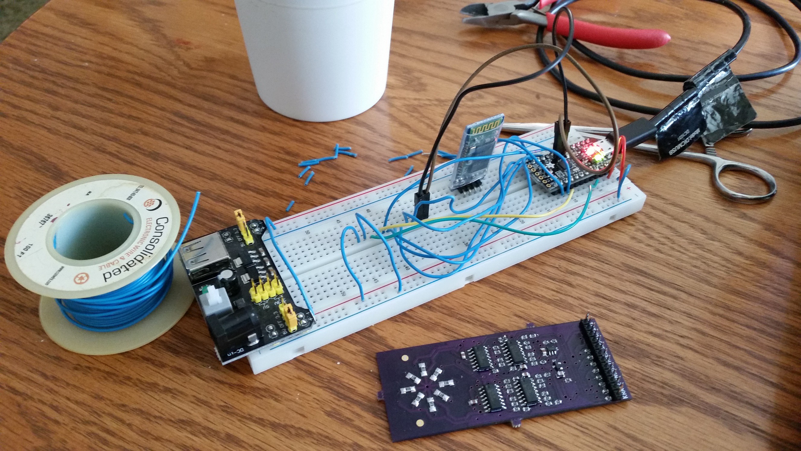
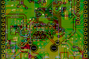
The thermistors are arranged in a circle on a flat section of PCB. A plastic shroud directs airflow over the sensors. The sensors are heated via controllable powere source from the micro. Wind travelling across the sensors causes small temp variations which are then measured and translated into wind speed and direction by the micro. The Opamp is used with a simple voltage divider reference as a difference amplifier, to increase resolution over a defined operating range.

Datasheet links.

Thermistor
http://www.vishay.com/docs/33017/tfpt.pdf

Opamp

http://www.microchip.com/mymicrochip/filehandler.aspx?ddocname=en540137
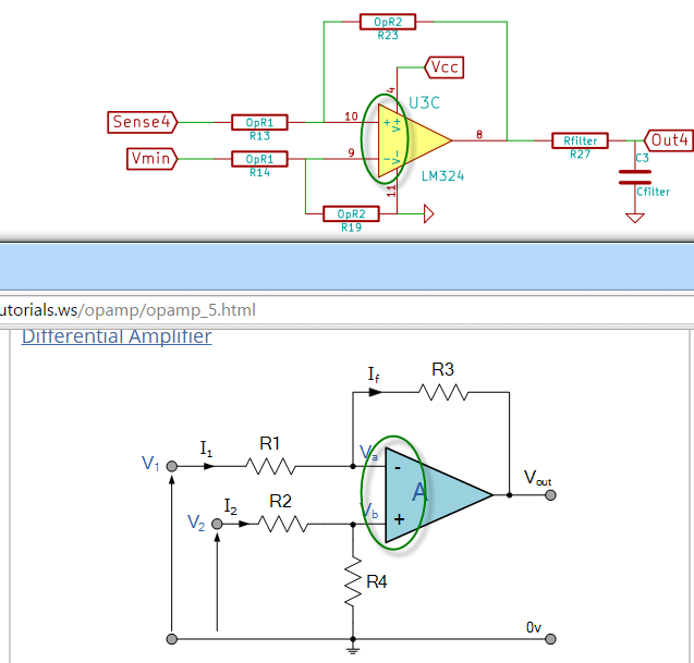
  • 4 × MCP6L04T-E/SLCT Quad Op Amp
  • 8 × THERMISTOR P 541-1167-2-ND THERMISTOR PTC 150 OHM 1% 0603
  • 1 × MCP6L01T-E/OTCT-ND Single op amp
  • 1 × Trinket Pro

  • Mistakes

    Christopher Kratz04/04/2015 at 14:39 0 comments

    Well I finally got back around to probing about my initial board, and I think I found another reason to respin this board. I think my differential amp is hooked up backwards! While probing I found that the output of my circuit was saturated right at five volts, which is the output of the differential amp that compares my references voltage divider to the thermistor divider. I'm not big on amplifier theory but if memory serves me, feeding back into the non-inverting input is probably a good explanation for the output saturation. I haven't given up yet, but I do have to rethink the design a bit. More to come.

  • Noise

    Christopher Kratz01/18/2015 at 02:09 0 comments

    What a lovely 5 MHz sine wave. Not sure why its coming from my crappy breadboard power supply, but hey, now I know I need more filtering. Maybe a lot more. That wave is about 0.2 V peak to peak, which probably adds up to a lot of noise coming through the OP Amps. A 10uF cap on the power rails quites it down (oddly, when I power on, its still there, but slowly fades off after about a few seconds). Also I replace the single Amp with the 10R variant of the part (not the U variant I thought it was). Except the outputs are saturated to the Amps 5v max. I'll have to probe all the points when I get a chance to see if I messed up the Amps, or if I just need to adjust the resistor values.

  • Trello

    Christopher Kratz01/14/2015 at 00:03 0 comments

    As an experiment, I threw a link onto the project for a Trello board I created for this project (https://trello.com/b/emRXO44l). Hopefully, for those who are following me, it will give a better sense of progress and give me a better sense of organizing what I'm doing.

  • Update

    Christopher Kratz01/10/2015 at 19:07 0 comments

    Well I figured out my one footprint problem for the single op amp. The datasheet mentions model variations 01, 01R, and 01U. Well my part ended in 01T which was confusing to me, but looking at the digikey parts again, T is actually at the end of every part number. I think I must have laid out the footprint for the 01U, but ordered the 01 variation. So I ordered the 01U variant and I'll put that on the board and try out my original design without feeding a PWM signal into the board for reference. Maybe that might solve some of my noise issue I was having during initial testing. I'll have to probe it with the scope as well to see if the noise is just in the micro, or if its coming from the board/test setup. I can play around with extra filtering too before I try the code based ADC noise fixes.

  • PCB Service Comparison

    Christopher Kratz01/06/2015 at 12:40 0 comments

    Since I bothered to order my first PCB from two services, i figured I'd post a quick comparison for reference. First and foremost, I noticed that that the DirtyPCB board had my mechanical holes I specified, whereas the OSHPark board did not. I didn't realize this, but when I placed the pad to create the hole, I selected 'NPTH, Mechanical', in KiCad, which for whatever reason spits out that into a separate drill file. Looking back in OSHParks FAQ, their service will only read one drill file and ignore any others supplied without warning, so be careful with that one. DirtyPCBs apparently is fine with multiple files.

    The second difference is color. OSHPark as you may know is the purple board. DirtyPCBs has options for a few colors, I chose the default red.

    Another point is that DirtyPCB stuck a batch label on the front of my. Small and inconspicuous, but different.

    The DirtyPCB boards also came with smoothed edges, whereas the OSHPark boards have the panel connecting nibs on them.

    The last board difference I can notice is that OSHPark has the gold plated finish on the pads, whereas the DirtyPCB ones are tinned.

    Finally of course, OSHPark is made in the USA and DirtyPCBs is made in China, which is a big difference in shipping times if you do the standard cheap shipping. DirtyPCBs had the boards made and shipped pretty quick though.

  • First Failures

    Christopher Kratz01/03/2015 at 02:52 0 comments

    While in theory the board almost worked, it mostly didn't. The first issue was I messed up the footprint on the single op-amp. Looking back at the datasheet there were three different pinouts for the SOT-23-5 version, none of which had a model that corresponded to the part I ordered. Outstanding.

    The first rev of this board was meant to be a quick breadboard proof of concept. After I had wired up an additional analog output from the trinket to be my reference voltage since i screwed up the voltage divider buffer amp, I had outputs coming from the board in the appropriate range. However after some poor probing I burnt out the 5V breadboard supply that failed into an open state, passing the transformer input to the 5v rail. While this worked OK, and quickly brought the thermistor temperatures very high, since the voltage reference wasn't working, the Op amps saturated and I just got max readings from the trinkets analog inputs. So I had to settle with testing with the 3.3V rail off of the breadboard supply, as the trinkets onboard regulator would get pretty warm trying to run the sensor. The mosfet control seemed to be working to control the voltage applied to the divider, but the low voltage supply didn't seem to warm up the thermistors at all.

    While I didn't have warm thermistors I tried to get some measurements anyway. Since the Trinket can program over the USB but not do serial over USB by default, I threw on this EBay Serial Bluetooth adapter, and loaded up a serial terminal on my phone. That worked OK for some quick and dirty output.

    It looked OK until this point. This is when the real problem reared its head. While I could measure a solid voltage off the output pin on my board with the multimeter, the analog inputs on the trinket were all over the place. Easy +/- .25 volts. This seems pretty odd as I had filters on the output from my board. I'm sure there is something I'm missing, but the board needs to be respun and redesigned anyways. Maybe the board could use that onboard ADC. Plus a well designed board should either plug right onto the trinket board, or just stand on it's own. Also on the redesign agenda would be to use NTC thermistors instead. For whatever reason the PTC ones I choose have a pretty small range of resistance and cost a lot.

    Anyways, today is the end of the contest entry period, so whatever I have at this point is my entry. Also to fulfill my obligation to the contest rules I'm currently uploading a video of myself rambling on about my project to and pointing at my breadboard for a few minutes. Riveting entertainment, I know, but its in the rules. I don't want to disqualify myself.

    Hopefully my next update will have some better results.

  • Everything is here, but I'm not.

    Christopher Kratz12/28/2014 at 01:32 0 comments

    Well I got the parts in from digikey, and the OSHPARK boards were reported delivered to my house, where I'm not. The holidays are a tough time to do a short turn project. I've setup my software environment and checked that in. I kind of like the visual micro extension for Visual Studio. VS community edition is free and we'll featured, Visual Micro is mostly free, the pro version has more features but I don't know what exactly. I haven't yet uploaded code to the Trinket so I don't have a definitive feeling of how well this setup works, but it's looking good so far.

  • PCB Races

    Christopher Kratz12/22/2014 at 16:06 0 comments

    Amazingly my Dirtypcbs.com order has apparently shipped already, so hopefully with the DHL shipping it will be here by Friday. My OSHPARK order was upgraded to expidited processing for free, and is at the board house. No ship notice from Digikey, although I ordered late Friday night. I'll have to experiment later with different thermistors, as I apparently picked the most expensive ones. I think the same board could be used with cheaper NTC thermistors, but some of those I looked at had much wider resistance ranges, good for measuring, but I need more information on how easy the devices are to heat up. I haven't sat down and tried to understand if I can calculate a temp based on power and dissipation. So experimental methods will be used. One thing I forgot about was the compas but I might have one of those laying about.

  • Parts Ordered

    Christopher Kratz12/20/2014 at 06:56 0 comments

    Well after calculation all the various resistor values I needed, the non-Trinket parts are on order from DigiKey. I've added a link to my BOM (its public if you have an account on their website), right next to the OSHPark and Dirtypcbs links. For now its off to writing the software side as much as I can without the hardware. That will mostly be setting up the structure, analog reads, output mechanism (I have one of those Nokia LCDs in the drawer I might use for this), and guessing at the algorithm with fake data.

  • Boards Ordered

    Christopher Kratz12/18/2014 at 19:14 0 comments

    Woooo! I've submitted my board layout and now I wait. I'm not quite sure how complete the project must be for the January deadline, but here's hoping I get them before the. For fun, and comparison, I submitted to OSHPARK (link to the board on the project) so it can be easily ordered by anyone. One of the tenants of the contest was easy replication. I also, after a quick Google search for alternatives, submitted an order ro dirtypcbs.com. 10 boards for $14 from China. Free standard shipping but I payed the extra 17 for DHL. I'll see which ones I'll get first. I may have to mock something up on the breadboard in the meantime to build the software.

View all 17 project logs

Enjoy this project?

Share

Discussions

Igor wrote 05/20/2017 at 20:36 point

Hi Christopher, 3 years since last activity in this project. Did your idea work? If yes, what's the software interface you used?

  Are you sure? yes | no

Clovis Fritzen wrote 12/09/2014 at 20:07 point
Great ideia, great project!. I hope you figure out the sensor calibration and all the other stuff. I'll be here cheering for your project to win!!

  Are you sure? yes | no

Muphins wrote 12/03/2014 at 13:08 point
The idea of measuring heat dissipation is not bad, but I think it would be much easier to use ultra-sound sensors.

  Are you sure? yes | no

Christopher Kratz wrote 12/03/2014 at 13:17 point
I had seen the ultrasound method when researching, but it seemed like the common method was measuring time of flight between the sensors, which may require the sensors to be far apart (at least for a pocket sized item). If need be, I can fall back to that method if this one doesn't work out. I'm hoping this method will give me a very small sensor, that at very least can tell direction if not speed reliably.

  Are you sure? yes | no

PointyOintment wrote 12/03/2014 at 23:29 point
The heat dissipation measurement technique is sound—it's what's used for high-precision flow measurement in wind tunnels, and car engines use it to measure their air intake—but I've never seen it done with thermistors instead of hot wires. I'm not sure it will work, but I guess you'll find out. (I assume you chose to use thermistors to get greater analog dynamic range to make measurement easier with the Trinket and/or because they're easier to drive.)

  Are you sure? yes | no

Christopher Kratz wrote 12/04/2014 at 19:44 point
Yeah, I was mostly worried I wouldn't be able to measure the difference in a standard thin copper wire. I assumed the wire methods were using special alloys. Although, I can always leave a space to attach a small wire on the PCB, just in case. My biggest worry is being able to heat the thermistor enough, which is the one part I can't really calculate ahead of time.

  Are you sure? yes | no

PointyOintment wrote 12/05/2014 at 05:16 point
Your thermistor's datasheet mentions a dissipation factor, so I looked up what that is. This page is somewhat interesting: http://www.cornerstonesensors.com/About.asp?PageCode=Dissipation

This Vishay document looks like it could be quite helpful—look at the bottom right of the first page in particular: http://www.vishay.com/docs/29007/ptcexpla.pdf

Also, here's a Vishay document on NTC thermistors that includes an example circuit for fluid flow measurement (Fig. 10, p. 7): http://www.vishay.com/docs/29053/ntcintro.pdf
I was thinking you might want to switch to NTC because the self-current-limiting effect of PTC (i.e. why polyfuses are PTC) could make self-heating power measurement difficult. OTOH, hot wire sensors are PTC, and your target temperatures are well within the linear band of your PTC thermistor, so maybe it won't be too hard.

  Are you sure? yes | no

Similar Projects

Does this project spark your interest?

Become a member to follow this project and never miss any updates