 Dan
Dan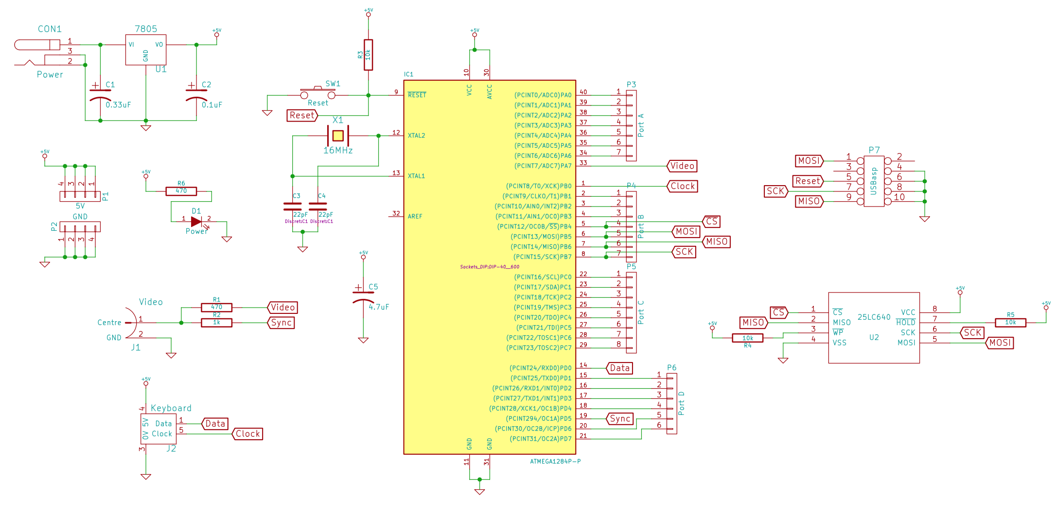
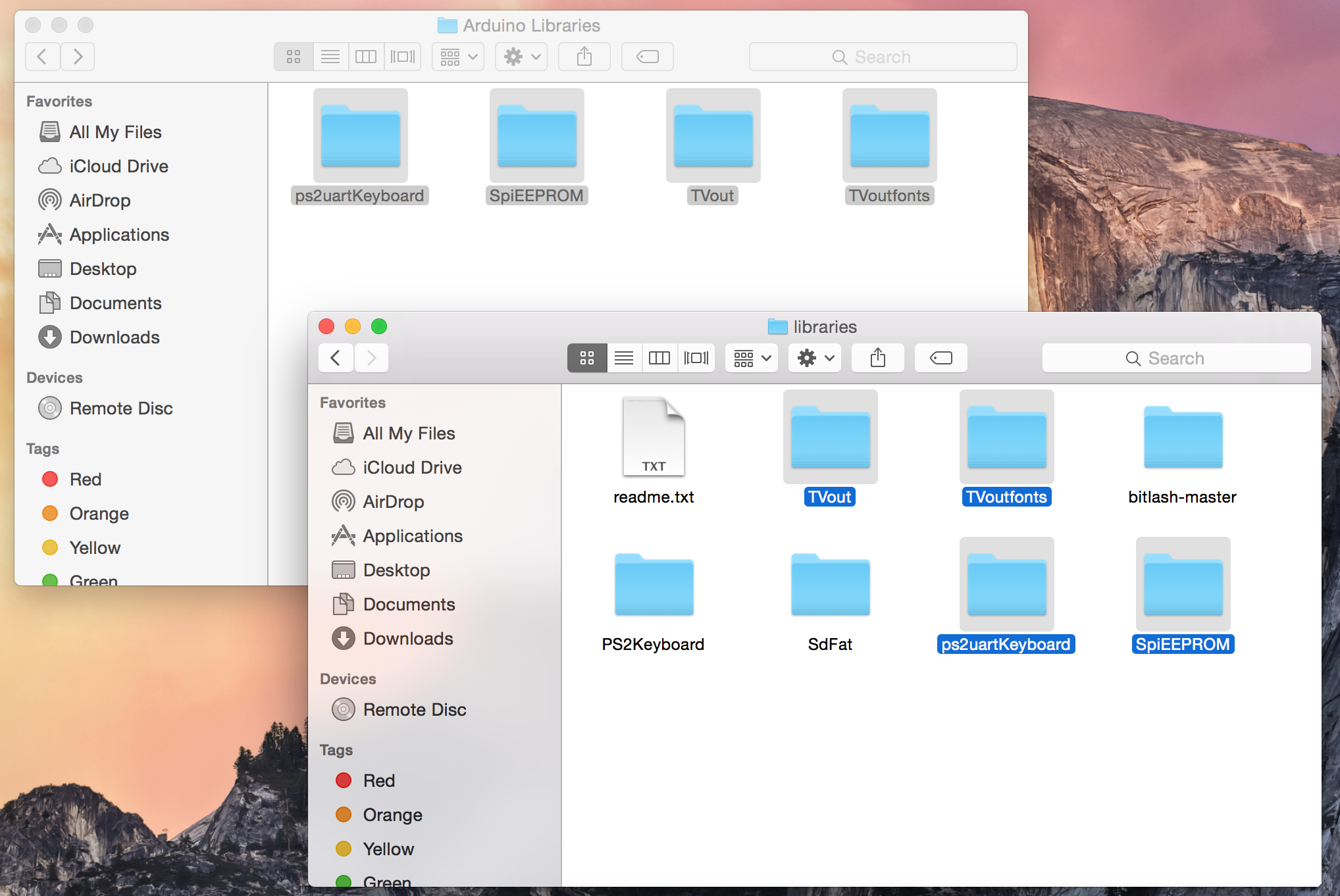
The above image shows the schematic for the computer, which was created in KiCAD. The circuit uses an ATmega 1284P microcontroller which was boot-loaded and programmed using the Arduino IDE. An 8KB SPI EEPROM IC (25LC640) is connected to the 1284P and used for storing BASIC programs as the 1284P only has 4KB internal EEPROM so an external EEPROM IC was used for larger program space. The 1284P is responsible for running the BASIC interpreter (TinyBASIC Plus), generating composite video (using the Arduino TVout library), reading PS/2 keyboard input (using the Arduino PS2uartKeyboard library) and talking to the EEPROM IC (using the Arduino SpiEEPROM library).. The circuit is powered via a 7805 voltage regulator allowing a range of voltage sources to be used to power the circuit (such as a 9V battery or 12V wall mounted transformer). A full list of components can be found under the 'Components' section of this page.
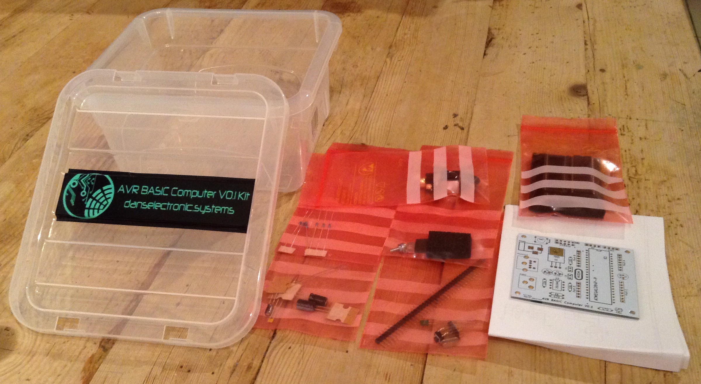
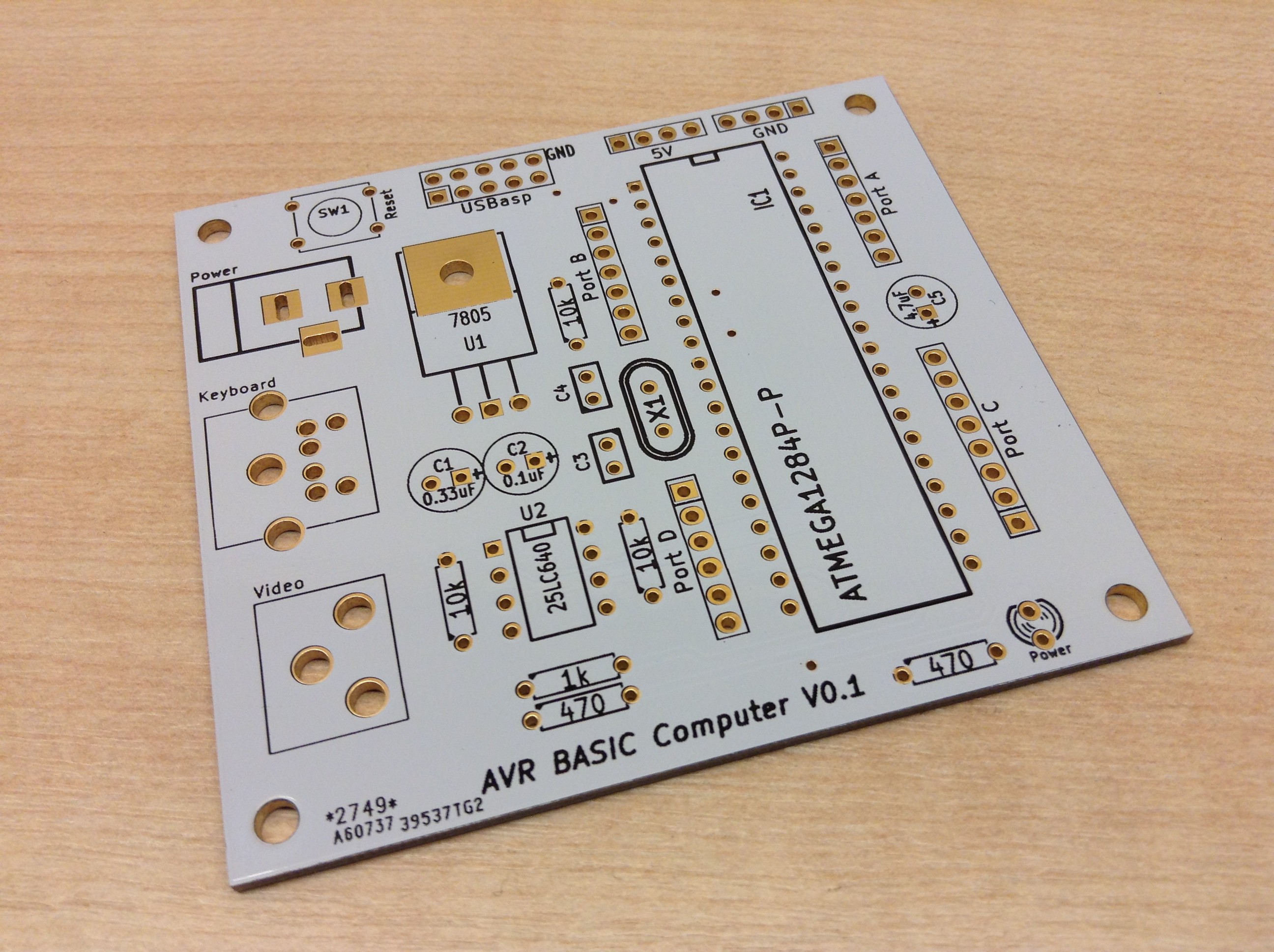
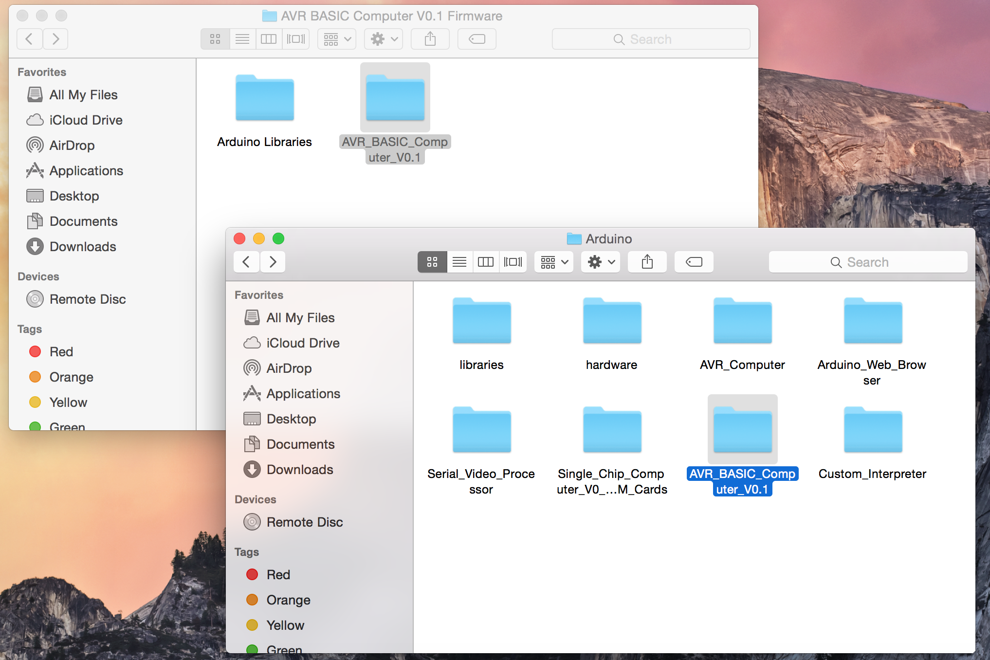
The computer is designed entirely using through-hole components making it easy to assemble at home. PCBs are available to purchase through eBay from me by clicking the 'Purchase PCBs' link on the left hand side of this page. Once a PCB has been purchased and the components gathered, the PCB simply needs to be assembled and then programmed. Programming involves using a USBasp programmer connected to the USBasp header on the PCB and following the programming instructions in the 'Build' section of this page (an Arduino can be used as the programmer for the circuit if required). The firmware (code), Arduino boot-loader and circuit diagram can be downloaded using the links on the left hand side of this page.
Some commands and BASIC program examples for the TinyBASIC Plus programming language can be found at the Github page for TinyBASIC Plus (https://github.com/BleuLlama/TinyBasicPlus). Below is a small list of some TinyBASIC Plus commands:
PRINT "hello world!" - Prints text within the " marks
MEM - Displays SRAM and EEPROM memory usage
NEW - Clear current loaded program from SRAM
LIST - Display the current loaded program
ELOAD - Load program from EEPROM
ESAVE - Save program to EEPROM
EFORMAT - Format EEPROM

A simple example program (with following commands):
10 print "hello world!"
20 goto 10
ESAVE
RUN

Note, programs saved in EEPROM are automatically
run upon boot. To stop any program running, press the ESC key.


 Sagar 001
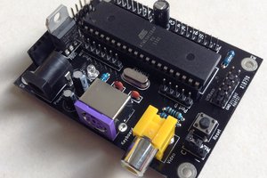
 adria.junyent-ferre
 Dhrupal R Shah
I have faced no such issues