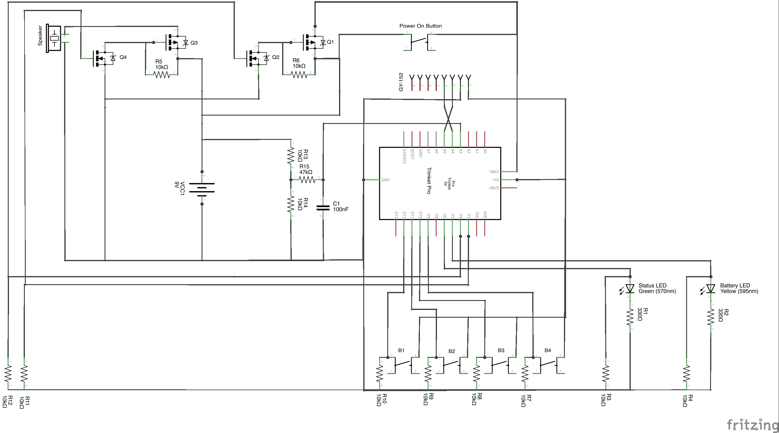
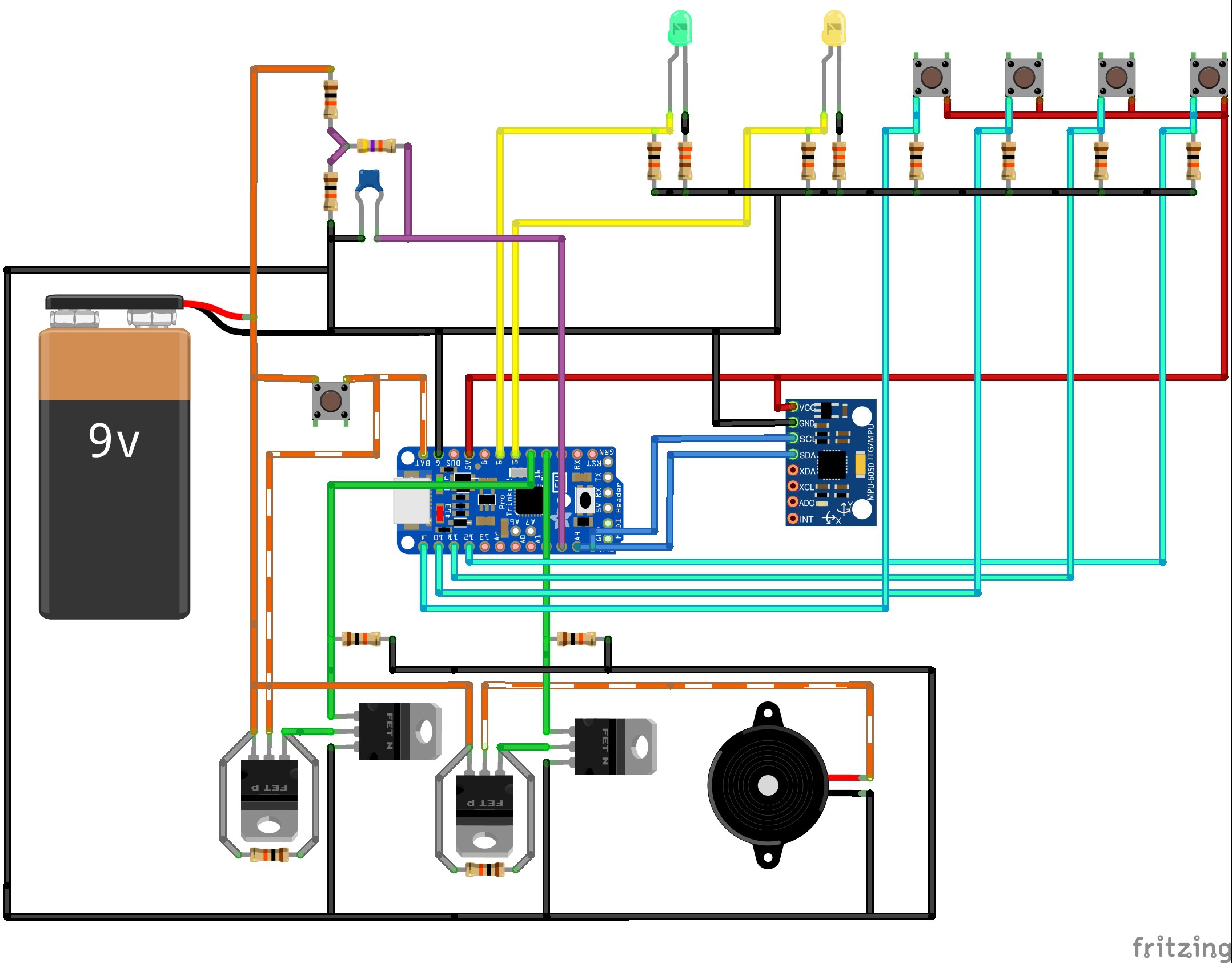
Core components are:
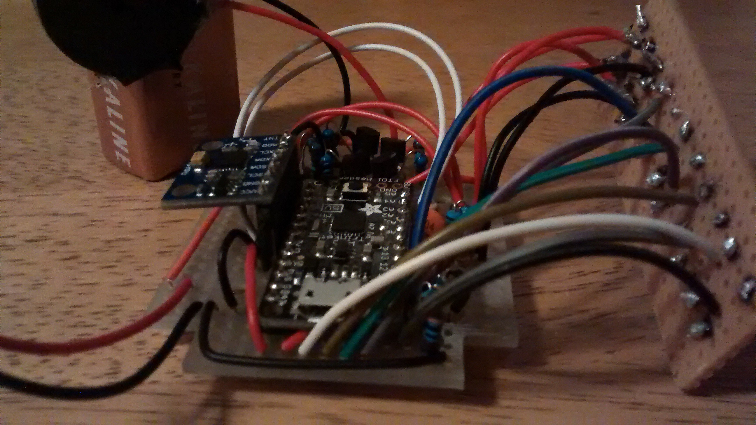
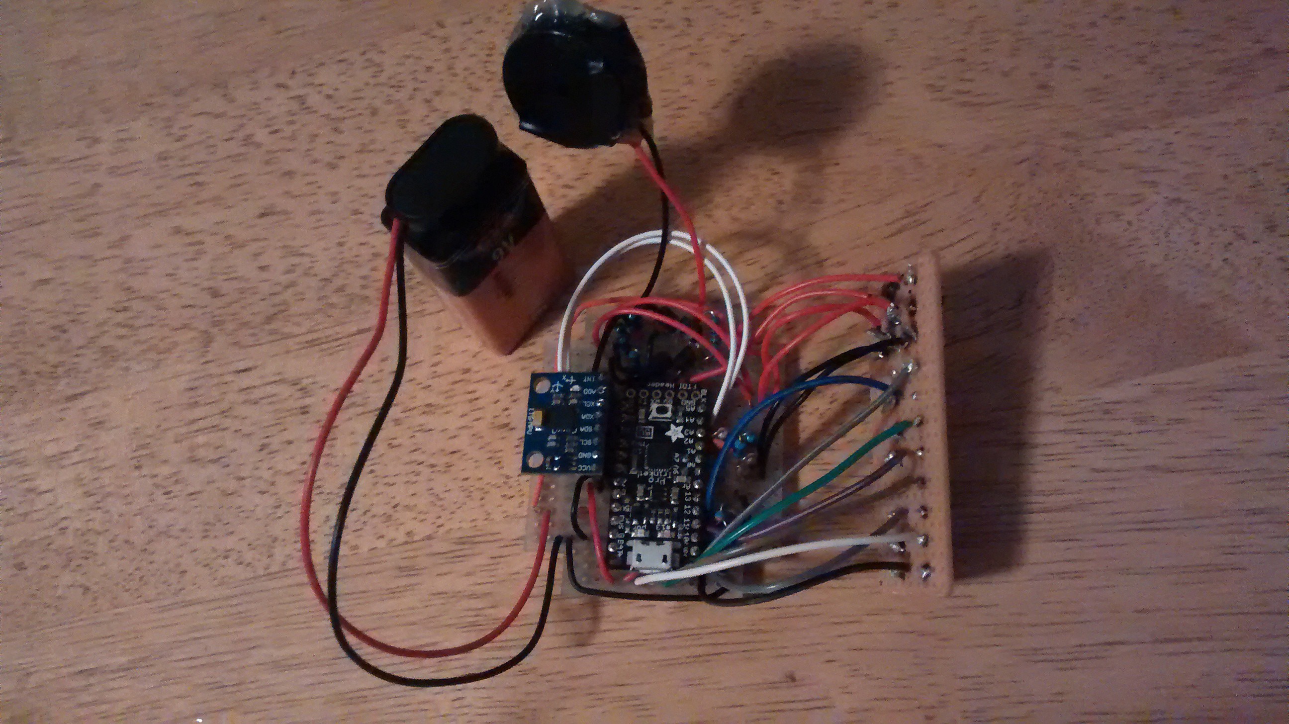
- A Trinket Pro as the brains of the show. You can get one at the Hackaday store.
- An accelerometer to tell when the device is moving. You can use a variety, but I used the GY-521 available here.
- A speaker/peizo to act as an alarm. You can use various depending on your preference for sound, but I used this one from RadioShack. I chose it based on the loud sound but low current consumption, and that it takes a broad range of voltages (3V-28V) so I wouldn't need to be too fussy about battery voltage.
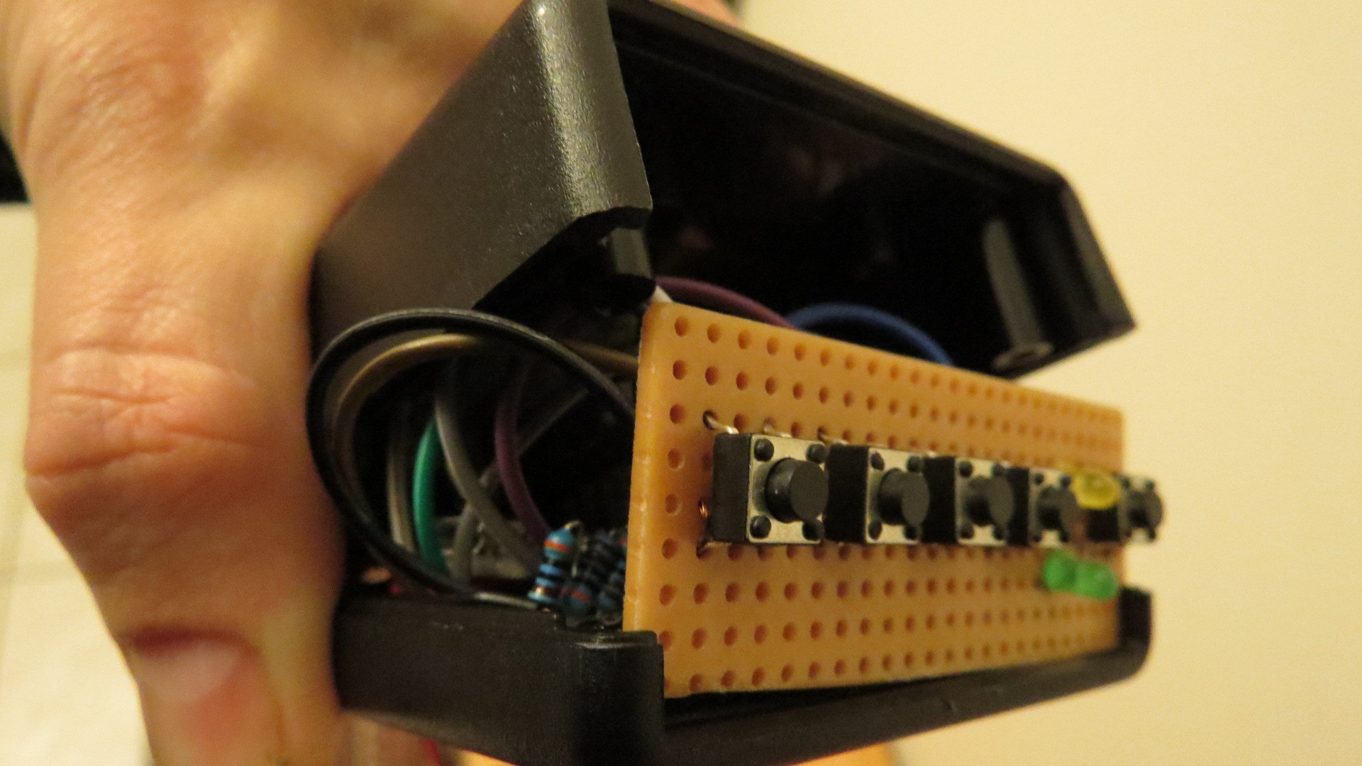
- Four buttons to input a code
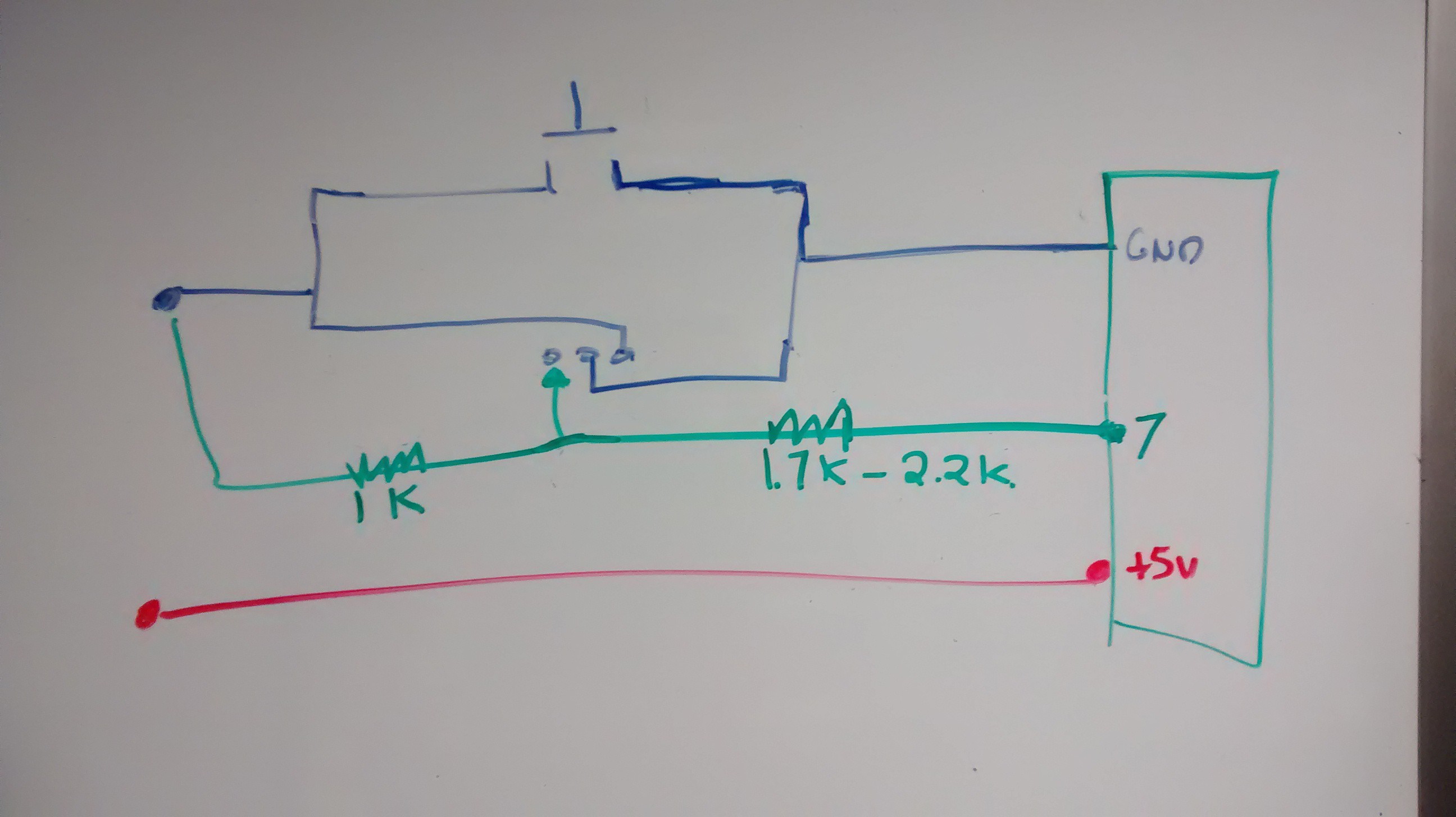
- One button to turn the device on, paired with a power circuit that allows the device to be turned on by hardware (the button), but off by software (by putting a pin to low)
- Two LEDs: one green LED to tell status, and one yellow LED as a low battery warning
Other components include:
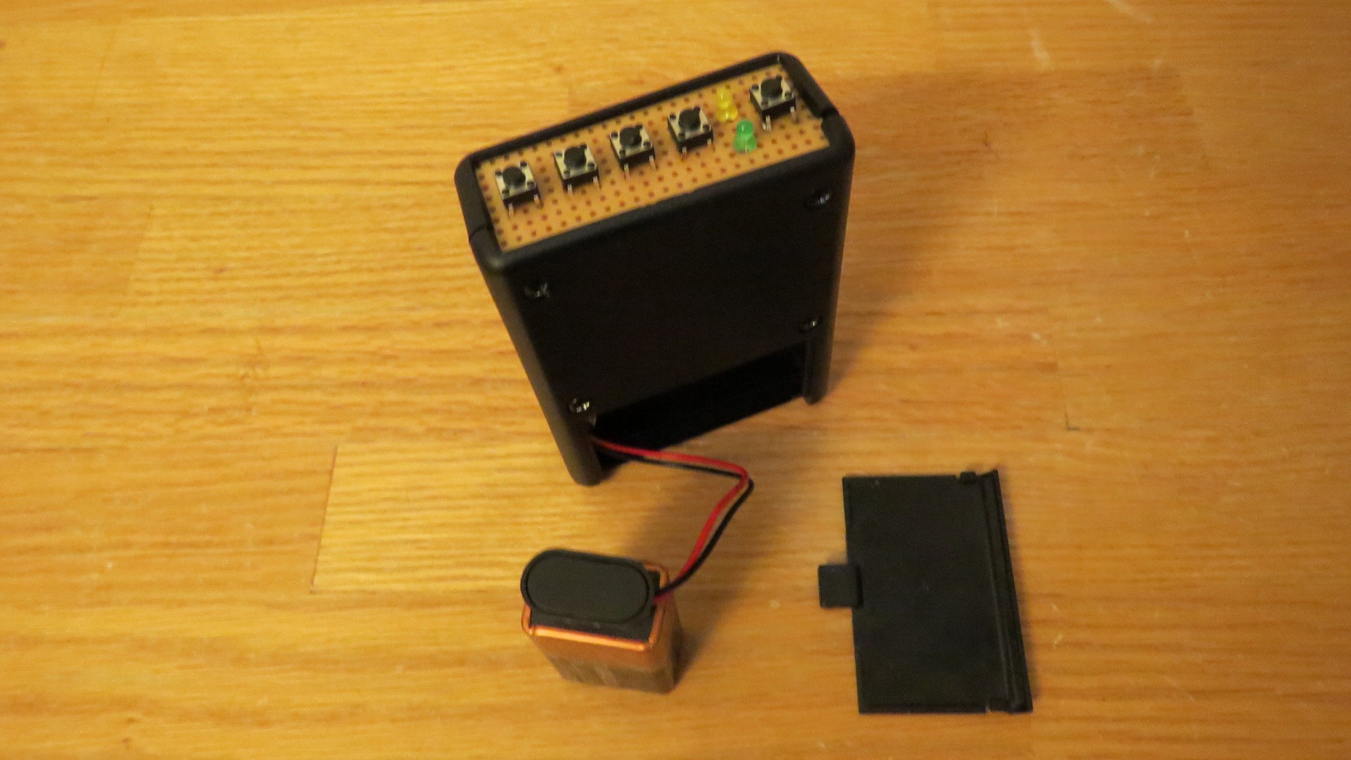
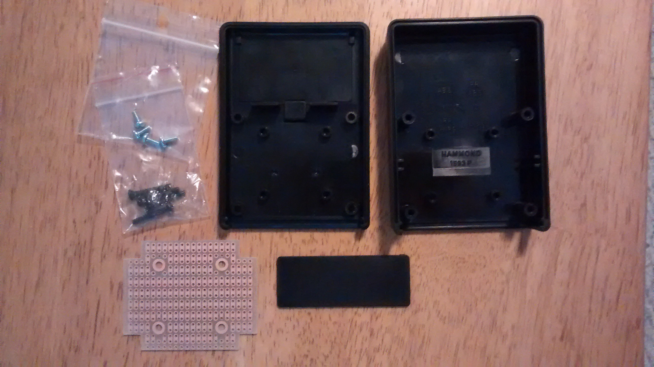
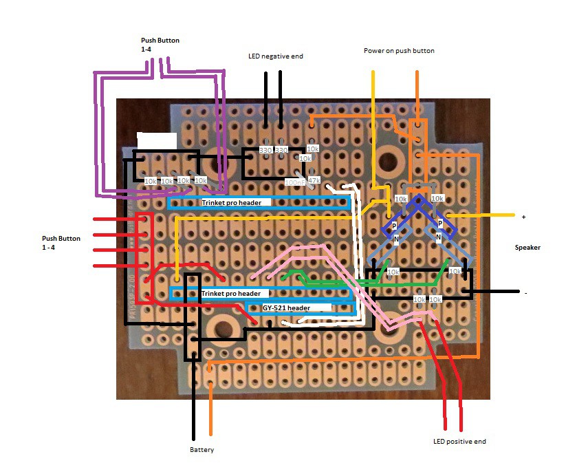
- Project box. I used a project box with an integrated PCB and battery compartment, available here.
- Piece of perf board (doesn't need to be very big, just enough to cover one end of the project box)
- 2x P-Channel MOSFET transistor. From Mouser here. These are TO-92 packages, so fairly small. The max current is below what I anticipate would ever be needed to power all the components.
- 2x N-Channel MOSFET transistor. From Mouser here.
- 2x 330 ohm resistor (for current limiting on the LEDs)
- 12x 10k ohm resistor (for ground ties, etc.)
- 1x 47k ohm resistor (for current limiting for the battery monitor pin)
- 1x 100nF capacitor (for dealing with any spikes on the battery monitor pin)
- 1x 6 pin female header
- 2x 12pin male headers (for the Trinket Pro, and may come with your Trinket Pro)
- 1x 9V battery clip
- 1x 9V battery
- Hook up wire (multi color if you want to keep things straight for yourself)
- some thin foam padding (e.g. from envelope padding). Optional, to make the battery fit more snug.
The user interface is:
- Device is normally off. Press and hold power button for 3-5 seconds to turn device on; wait for the Status LED [green LED] to turn on.
- After powering up, Status LED will blink for [10] seconds. During this time the user must enter the [secret code]. This is to ensure against turning on accidentally as well as to ensure that user remembers what the code is before the device gets armed. If the user does not successfully enter the secret code during this time, the device turns itself off.
- After successfully entering the code, the Status LED will turn solid on. This indicates that the device is giving the user time to put the device stationary, in this sketch [20] seconds.
- The Status LED turns off, indicating that the device is now armed and listening to the accelerometer. If there is movement, the Status LED blinks slightly to indicate movement.
- If there is movement for more than [5] seconds and above [threshhold], the alarm goes off and turns the Status LED solid on. The alarm stays on until the user enters the secret code.
- Once the device is on, if the user enters the secret code after or during the settling time, the Status LED will blink once long, then three short, and then then the device will turn itself off without turning the alarm on.
- If the battery is low voltage, set as below [6.5] volts, then when the Status LED is turned on in step (1) or in (5) or (6), the Battery Low Voltage LED [yellow LED] will turn on solid on.


 Edgar
Edgar
 Jean-François Poilpret

 SimpleTronic
Thanks, much appreciated!
Will post a video of the final project in action shortly!