While I am waiting for my parts to arrive, I decided to work on designing the power circuit of the project.
A key part of the project is that you can hit a button to turn the board on, but hitting the button again does not turn it off. This is to prevent the thief from being able to turn the alarm off by simply hitting the on/off switch. I also wanted to have it so that the device would completely power off when not in use, not in a sleep mode or similar waiting for the arm button to be pressed.
I decided to make a circuit where the power from the battery would flow to the board by one of two ways:
1) a button
2) a transistor, which is controlled by digital pin on the microcontroller
The basic schematic is below: (the 7 is just because I used that pin when testing the circuit)
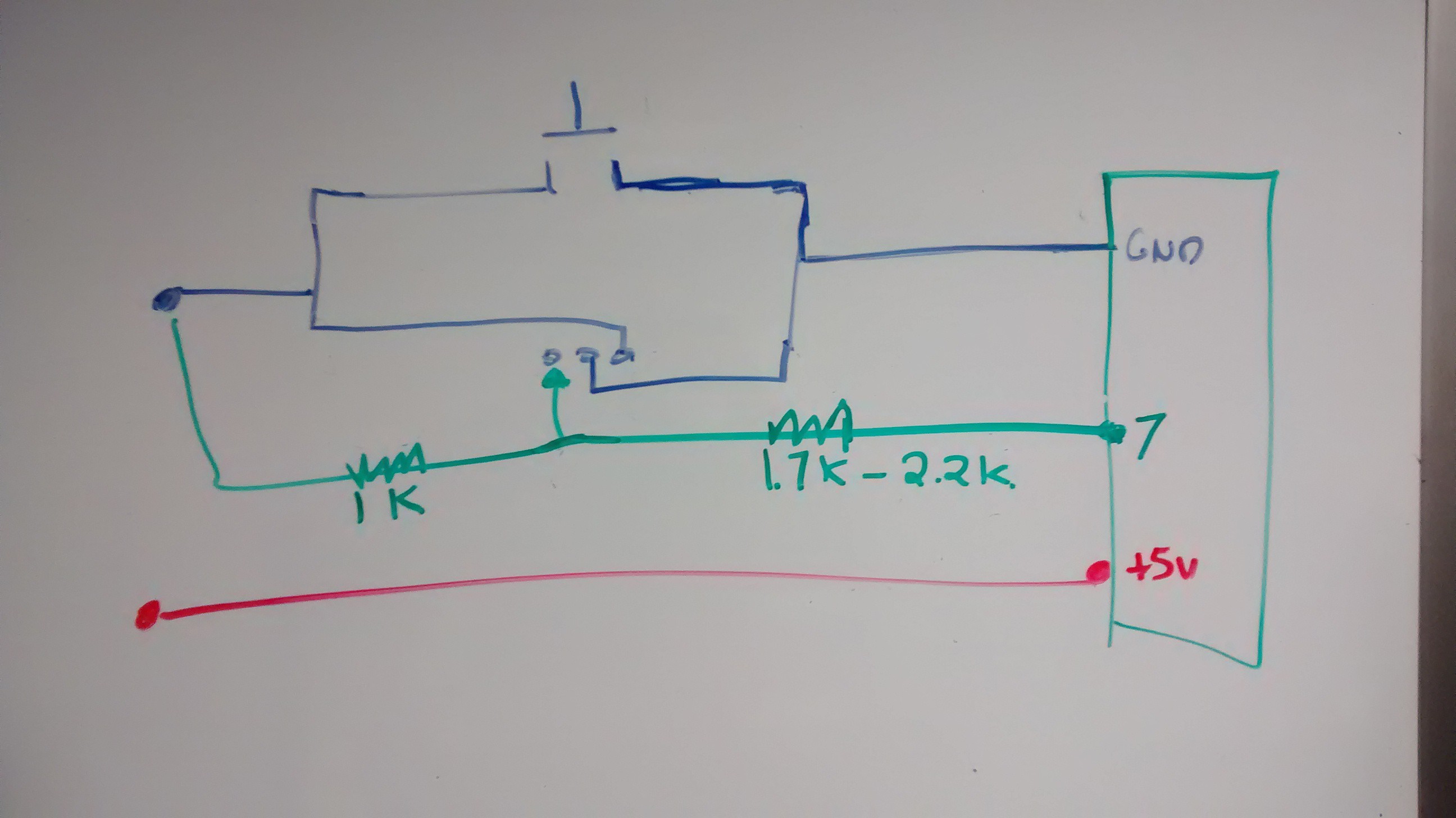
The transistor is an N-channel power MOSFET transistor, available here: https://www.adafruit.com/products/355?&main_page=product_info&products_id=355
Way over kill for this project, but it was what I had on hand. I imagine I can replace it with a ZVN2110A, which I can get from Mouser for less than a dollar. I anticipate relatively low current needs for this project, so that transistor should be able to handle it.
I also put in a 1k resistor to tie the gate of the MOSFET to ground (which was expected, and designed to keep that part of the transistor circuit normally off), but was not expecting to need to put in resistors between the digital pin on the microcontroller and the MOSFET gate. After some experimentation, I found that a resistor of between 1.7k and 2.2k did the trick. So I put in two 2k resistors when I constructed the circuit on the breadboard.
In the sketch, I have the digital pin that is tied to the MOSFET gate (in my case, pin 7) pulled to HIGH in the setup, so the MOSFET gate opens nearly as soon as the button is pressed. When the button is depressed, the MOSFET remains on and power continues to flow to the board. Further presses of the button have no impact. The circuit stays on until I decide to put the pin LOW, turning off the circuit completely and de-powering the board. In the test circuit, this occurred 5 seconds after the board turns on, but in the actual project I will program it to do so only when the correct 4-digit code has been punched in.
Discussions
Become a Hackaday.io Member
Create an account to leave a comment. Already have an account? Log In.