 Elecia White
To make a ring, I needed to minimize everything. Of course, if you've seen the picture, you already know I didn't actually minimize much.
Still, batteries in wearables are a pain. For this wearable with my "you have to take it apart to charge it" methodology, well, longer battery life means this hack will exist longer. The more I take it apart, the more like it is that I'll repurpose the parts to do something else. (I have this idea for a different ring…)
Minimizing power in Arduino is a topic that has been taken on by plenty of other people. And I happily reused their code and methods (Thank, you Nick Gammon!).
However, when planning a device, it is helpful to determine the size of battery you need. To that end, I made an Excel sheet (sorry, I default there) which I've put into a Google spreadsheet so you can see it with the math. The first sheet (words) describes the process in words. The second sheet (numbers) reflects the same information but with numbers. You fill in the orange boxes, it generates the green one.
The first step is to determine the different power states of the device. For Wordy, it is either on (display showing) or sleeping (Arduino asleep, accelerometer configured to wake and interrupt it).
My next step was to figure out how much time the system would spend in each of these states. My goal is for the ring to be on for about five seconds every five minutes. Sometimes it will be on more, as I play with it a lot. More often it will be sleeping, such as left on a table overnight. (Note: if you build a Wordy, I strongly recommend setting the ring so it will lose at Pong. Sometimes if you leave it on the X side with no Y tilt, the ring will play Pong by itself indefinitely.) Starting with the idea of five seconds per five minutes means I'll probably be on the conservative side (unless it plays a Pong marathon without me).
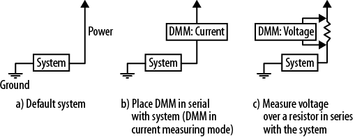
Next, I measured how much current each state. I used my shiny new DVM-with-current-sensing (my old one didn't have that (though it did have a more melodious beep in resistance mode)). You can use a resistor if you feel like doing it old school style.
(This pic is from my book. If you were unaware I wrote a book, well, yes, I did and it is full of jokes. And dinosaurs. But mostly embedded systems.)
Finally, I calculated how long the device would last given a 40mAh battery (the largest I was willing to use due to size constraints). The result turned out to be much greater than I expected.
This does not have to be the order of events: you might start with the idea of how long you want the device to last and choose the battery accordingly. Or you may have a fixed battery and a predetermined life and need to determine how much time you can spend in each state. Happily, the math works in all the different ways.
Note that this value I got was greatly in excess of my self-imposed goal (which was a puny two hours). It is also greatly in excess of what I said in the build instructions (which was 48 hours). My wear-time was even greater than the estimated value: I charged on Tuesday afternoon and it died on Saturday night.
Though, I'm pretty sure I can do better than these power numbers.
When I measured the MicroView without the accelerometer, the on-state power fluctuated between 10mA and 14mA, depending on how much of the screen was lit. (All current measurements were taken around 3.7V.) If I modify numbers on the spreadsheet, the on-state power of 10mA to 14mA, it changes from 3.5 days to 3.1 days. I switched it back to 12mA as reasonable middle ground.
The accelerometer doesn't add much to this on-state value. On the other hand, for the sleep-state power, it is a very different situation. The MicroView alone took 0.14mA. The MicroView and accelerometer together take 0.31mA. If I change the sleep-state power from 0.31mA to 0.14mA, the amount of battery life expected changes from 3.2 days to 4.9 days.
The accelerometer datasheet says the accelerometer's current consumption is 6uA to 165uA. Looking at the numbers above (0.31mA-0.14mA = 0.17mA ~= 165uA), it is clear I should be able to reduce the sleep-state power by reading over the accelerometer datasheet again. (There is also an application note about wake/sleep features.)
Skimming through the app note, I don't care too much about the precision of the data (though I might in Pong mode but that is an active mode so it is ok to use more power there). It would be no problem to turn the system from 14-bit mode to 8-bit mode.
Sleep mode is limited to 50Hz sampling but that is what I'm sampling at anyway. Why am I still seeing the max current?
Ahh, according to the oversampling chart, I may see 165uA due to high resolution sampling. I can go to 24uA with normal sampling or 14uA with low power. However, I want some filtering either through oversampling or via the low noise setting. The combination of low noise + low power is back to 24uA.
Making only one change (from high resolution to normal sampling) should be enough to increase my battery life from 3.3 days to 4.6 days. That's exciting. Excuse me, I need to go see if that'll work and what else I need to change.
Discussions
Become a Hackaday.io Member
Create an account to leave a comment. Already have an account? Log In.