Alex Bowen
Much of this course has involved writing code in a virtual setting, and running it on a platform that shows the immediate physical effect of what was written on an electrical circuit using the Arduino microcontroller platform. With this in mind, I decided to choose a project that would be a challenge in both the electronics and programming aspects.
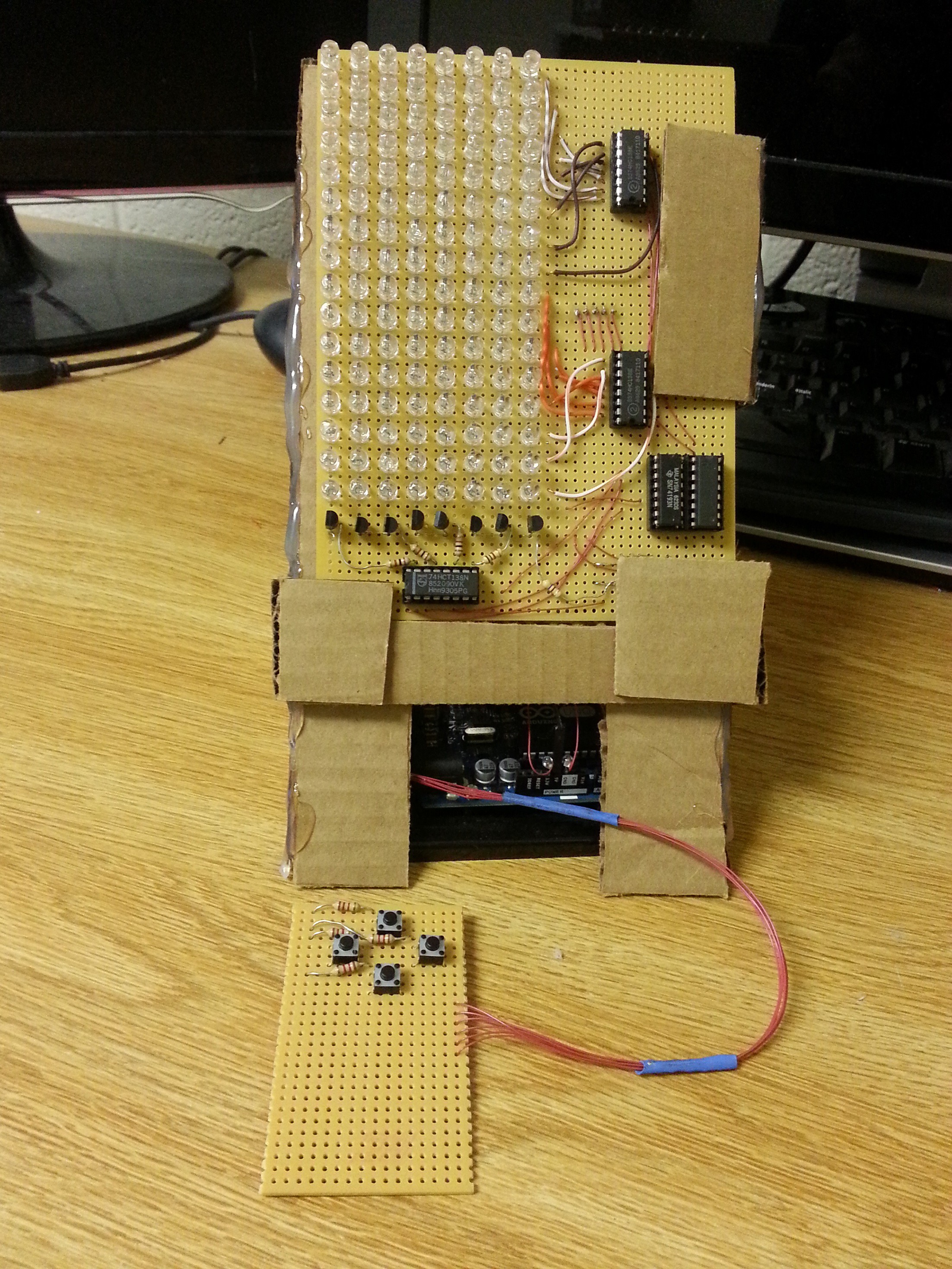
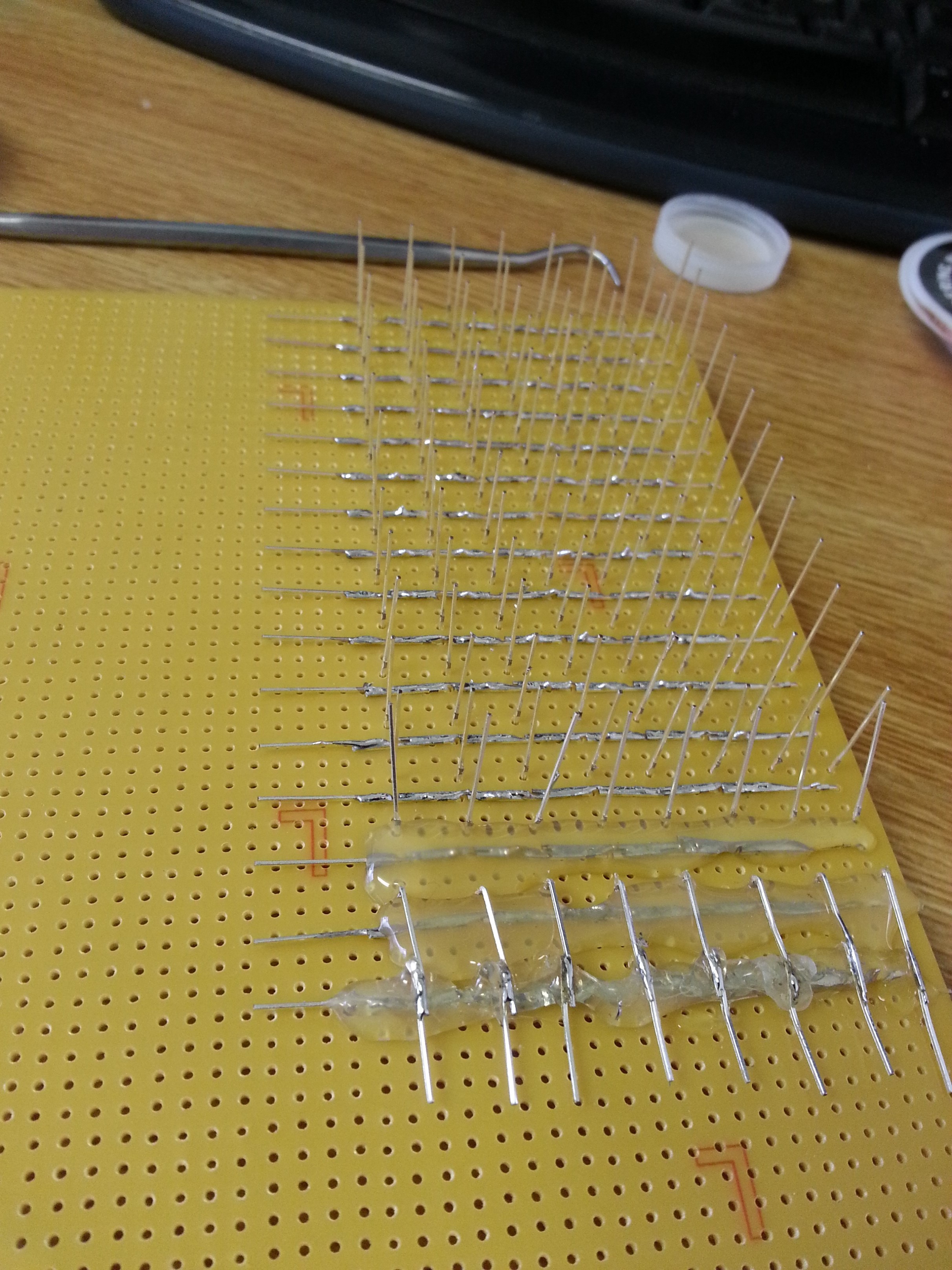
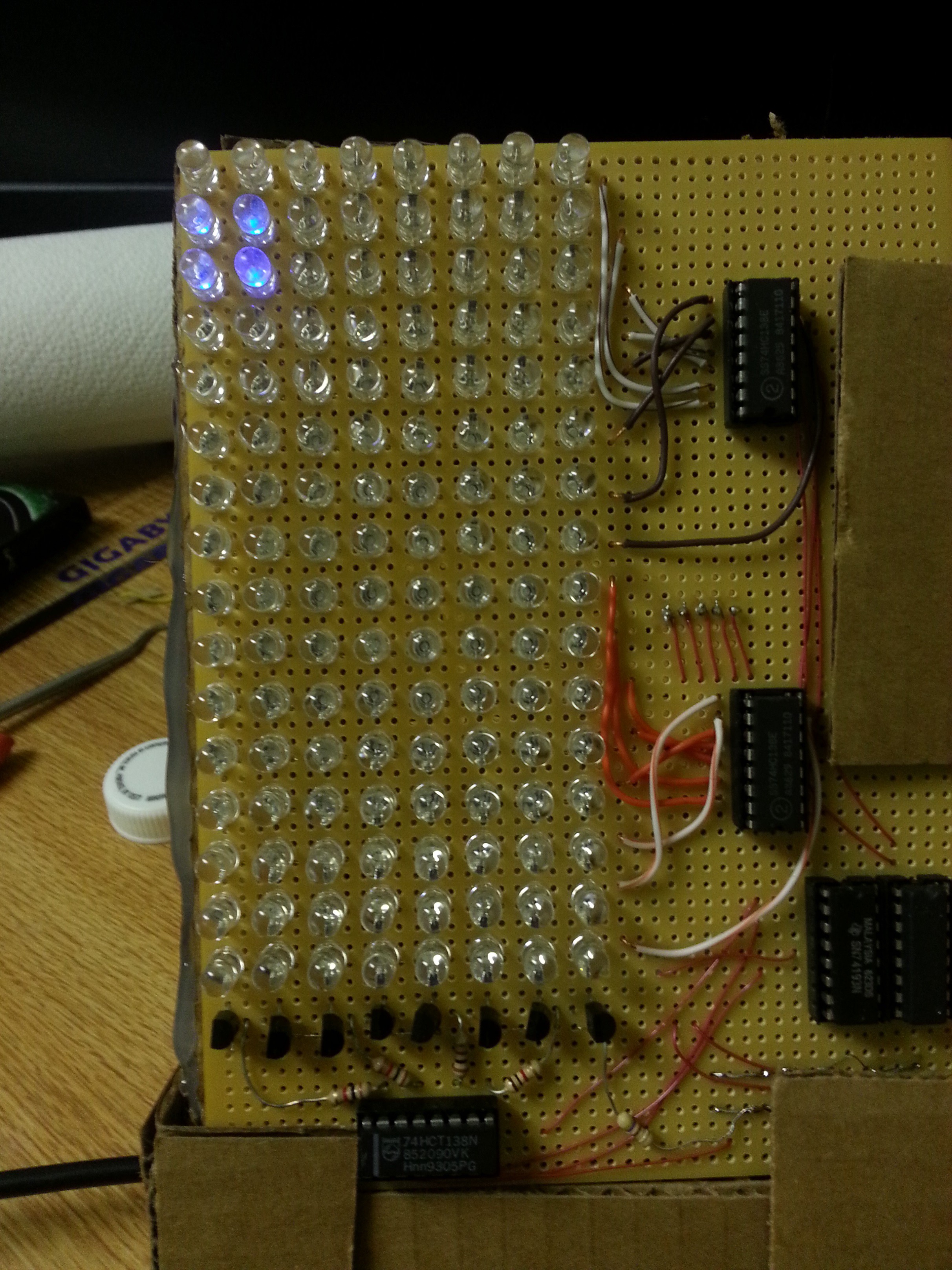
For the electronics aspect, I wanted to create a circuit that could wrap up some complex functionality into a simple interface back to the Arduino microcontroller. The eventual design led to the decision to build an eight-by-sixteen pixel LED matrix. In an LED matrix, LEDs are arranged into a grid of rows and columns. In each row, all of the cathodes are connected together, and in each column, all of the cathodes are connected. In this arrangement, applying a positive voltage to a column lead and grounding a row lead will light up one LED in the matrix. This can also be implemented as row-anode column-cathode, and in a square matrix this decision can be made arbitrarily.
Since it is only practical to light one LED at a time, each LED in the matrix has to be scanned at a high frequency in order to build up an image relying Persistence of Vision. Since the Arduino board does not have enough discrete IO to handle the eight columns and sixteen rows, I needed some sort of simple interface. First, the row lines were made accessible using a four-bit address fed into two 74138 decoder/multiplexer ICs. These ICs take a three-bit input, and will turn seven of its outputs high and one low, depending on the number. They also have two enable lines, one active high and one active low, and I hooked the highest-order bit of the four-bit address to the positive enable of one IC and the negative enable of the other. The 74138 was also used to address the columns, but since its outputs are inverted, I had to link them via 1 kilo-ohm resistors to the bases of PNP transistors that switched on and off the positive voltage supply to each column. This interfacing requirement was why I chose the column-anode approach, since I would have needed twice as many resistors and twice as many transistors to drive the row-anode approach.
At this point, it only takes seven bits to address an LED in the matrix, but that would still take up a lot of room on the Arduino board, and it would waste a lot of CPU time to manually change these pins to the desired output. To simplify this down even further, I employed two 74193 counter ICs. Each of these ICs generates a four-bit number that can be incremented, decremented, or reset to zero. They have borrow and carry lines that allow multiple ICs to be chained together to make bigger numbers. Using the lowest seven bits of my resultant eight-bit number, addressing an LED has now changed into either resetting the circuit to reach the first one, or pulsing it to point to the next LED with rollover. These two lines are what go back to the Arduino board, along with the active high enable line from my column decoder, which is what has the actual control over the state of the currently-pointed-to LED.
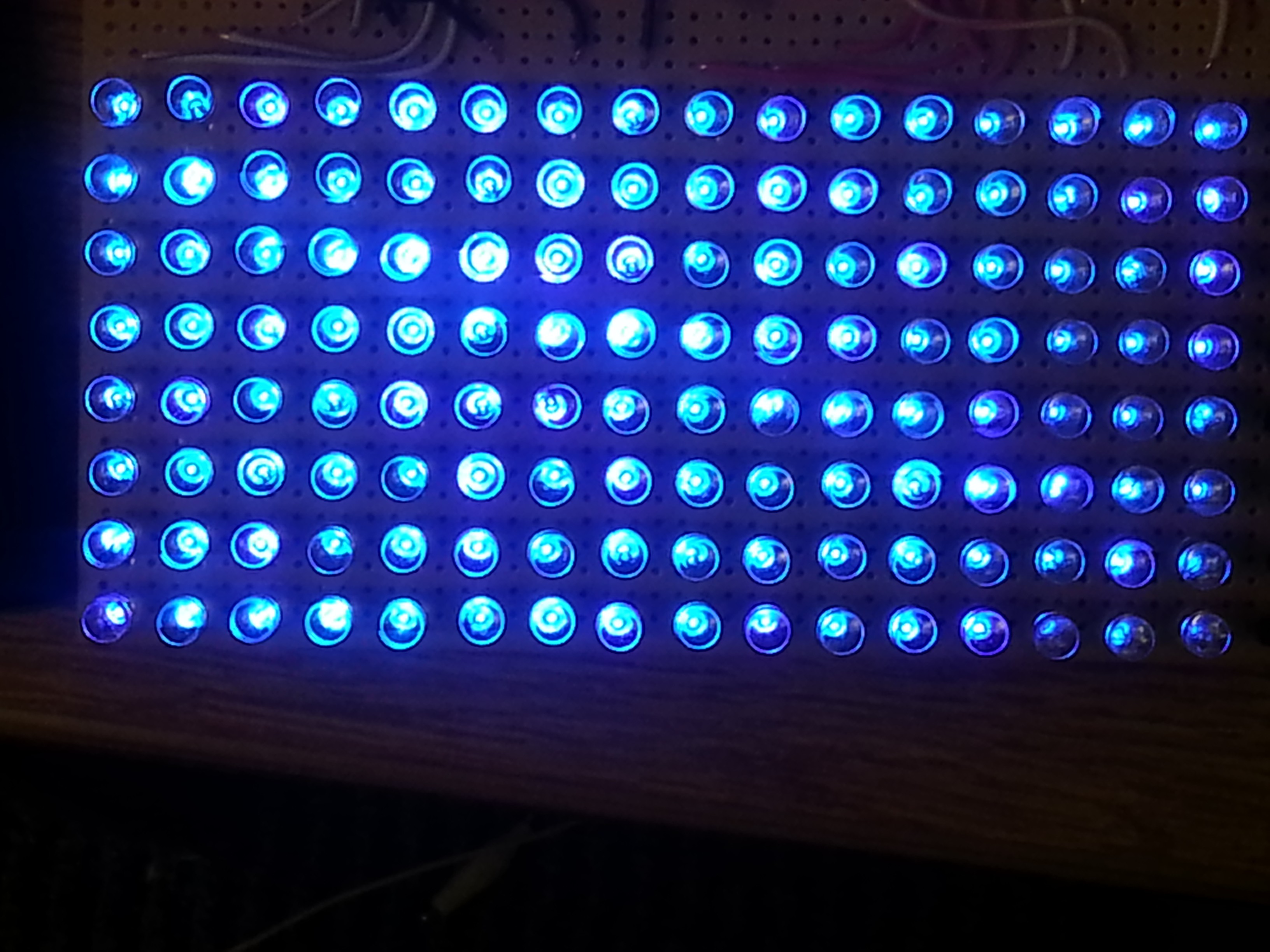
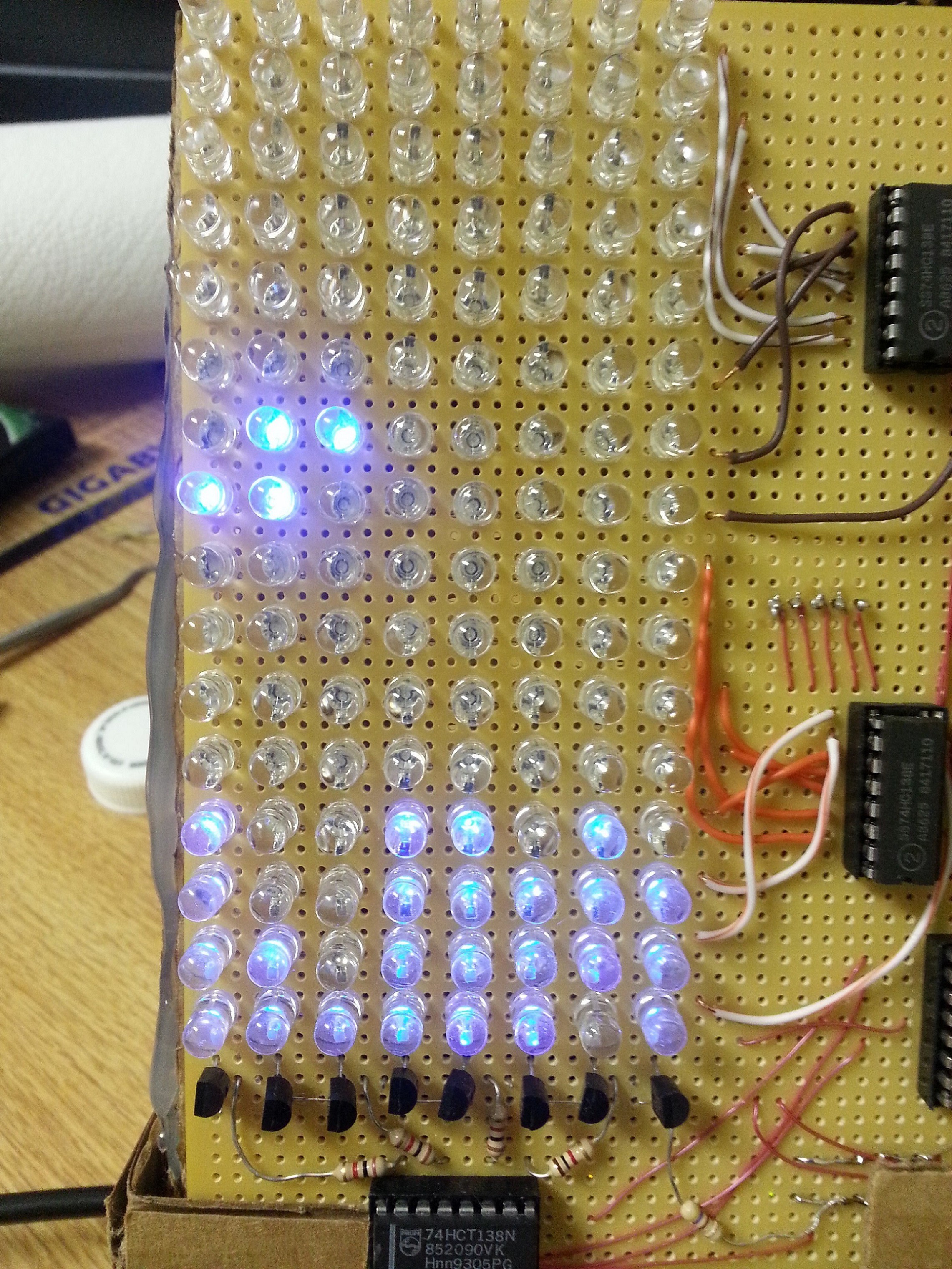
To display an image on the screen, the Arduino program has an array of 128 bytes (which I call a "frame buffer") with values set to the built-in HIGH or LOW values usable with the digitalWrite() function. The basic loop to place the values of these bytes is to write the value in the array at the current index value to the IO pin connected to the column select enable pin, wait a certain amount of time, turn the pixel off, then pulse the increment line low and then back high to point to the next pixel. This is what my first test program did, with a simple pattern manually defined in the frame buffer.
Since just displaying a simple image is not very impressive on the programming side, I decided to implement some kind of game that would be playable with an attached controller (which is just a chunk of perf-board with four tact switches). The first step in doing this was to find a way to interweave the time-sensitive LED matrix refresh cycle into the code for the game logic. Luckily, the ATMEGA 328 (like many other microcontrollers) has a built-in timer module that can be configured to generate a CPU interrupt at a set interval. An interrupt is basically a subroutine that gets called immediately when triggered by an external input.
The Arduino library for setting this up (called "TimerOne") works by calling the initialize() function and passing in the number of microseconds for the timer period, and giving the name of the function you want to run to the attachInterrupt () function. In my case, I run "IOInterrupt" once every hundred microseconds, and I adjusted the sequence of events so that the time in-between the interrupts is the time that the current LED is on or off, and the game logic code can run in that downtime.
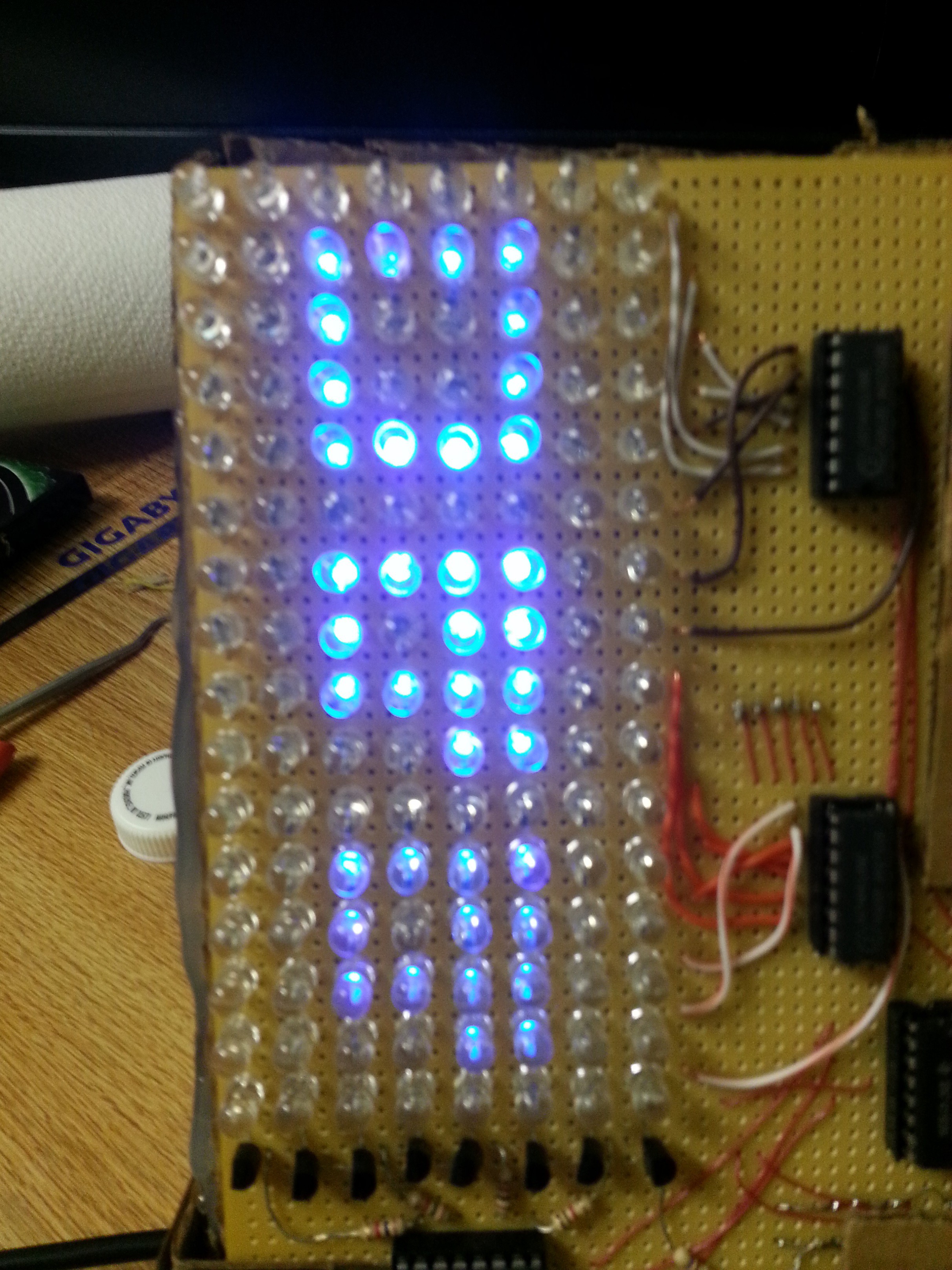
The game that I decided to implement for this platform is "Tetris," a puzzle game originally designed by Russian programmer Alexey Pajitnov in 1984. In Tetris, puzzle pieces made up of four blocks fall steadily down, and the player must move and rotate them into positions such that, when they stop falling, the blocks link up into horizontal lines and are removed, while blocks above the line fall down. The game is over when the blocks fill up to the top of the screen, and new puzzle pieces cannot be dropped.
I chose this concept because it can be represented very clearly on an LED matrix. When an LED is on, that space is occupied by a block. The runtime data for the game is stored in three arrays: one 128-byte frame buffer, another 128-byte array that represents the blocks that have stopped falling and been placed, and a 16-byte array that represents the 4-by-4 sprite of the piece the player is currently controlling.
With the screen refresh now squared away in my interrupt service routine, the game loop is now to clear the frame buffer, copy over the game field values to the frame buffer, copy the game piece sprite to the frame buffer at a given X-Y coordinate, and wait for either the player to give an input or a timeout to drop the piece down one square. When the piece reaches the lowest possible point, it is then written to the game field array so a new piece can be spawned. Before the new piece is spawned, the game checks to see if any complete horizontal lines were created, removes them, drops the blocks above them down, and increments the player's score by the square of the number of lines found in that round.
The player can attempt to move the piece left or right, rotate it around clockwise, or move it down faster without waiting for the timeout. Before this can be done, the game has to make sure it is a valid move. To do this, it creates a theoretical piece at a theoretical X-Y location, and tests that it fits within the bounds of the game field and it does not have a "HIGH" value at the same location as any "HIGH" value in the game field array. The move is not made if it finds a collision. If the attempted move was "down," and the collision test comes back positive, the game knows that the piece has reached the bottom.
This test for a collision is also done before the piece is ever put into play. If the test is positive at this point, then the game field has filled up and the game is over. The screen is not cleared and the player's score is displayed. To show the score, the game does some modular arithmetic to determine the three base-10 digits, and displays them as three four-by-four-pixel sprites written to the frame buffer, and a new game starts up after a few seconds.
The game's pieces are all pre-defined in a large array. There are seven pieces that can be rotated to four orientations that are stored in seven-byte chunks, giving an overall array size of 448 bytes. These pieces are retrieved with a function that calculates the appropriate starting index in this array from a piece number and a rotation number. The piece number of each new piece is determined from the random number generator, and the rotation always starts out at zero. The method copies the sixteen bytes starting at that calculated address to the given byte pointer. This same concept is used for the sprites for the digits in the score, only without the rotation concept. These ten digits occupy a 160-byte array.
Overall, this project went quite well. The only major hiccup that occurred was when a small glob of solder had melted its way through the hot glue insulating the column rails from the row rails, a defect that cost me a lot of time to diagnose and repair. I did also forget to check that the LEDs I chose were diffused, and as a result, the display has a fairly low viewing angle. I thought about correcting this by adding capacitors between the transistor outputs and the anode rails so that each LED would maintain its state for a full refresh cycle, but I would have needed just the right values for them to discharge at the right rate to make a noticeable difference without causing ghosting in the image.
The code actually turned out simpler than I had thought. I figured that clearing and re-drawing the game pieces would be slow enough that I'd need to swap between two frame buffers with each change, though even with a full game field, it still happens fast enough that this is not necessary. It did take a while, however, to figure out the best amount of time for the refresh cycle. Below 100 microseconds, the brightness of the LEDs was unsatisfactory because there was nothing displayed for the duration of the interrupt routine, and above 100 microseconds there was a noticeable flicker in the display. This flicker is actually still picked up on camera at the 100 microsecond interval.