 Jac Goudsmit
The L-Star project is an open-source single-board computer design that uses a Propeller microcontroller to control a 65C02 processor. You can use it to emulate early 6502-based computers such as the Apple-1 or the OSI Challenger, or you can invent your own 6502 computer.
All the parts that are needed to put an L-Star together are available in through-hole packages, so you can build it on a breadboard, or on a Propeller proto board. Or you can order a kit on Tindie (click on the Tindie link on the project page), which has some extra features such as a 128KB static RAM chip and an expansion port.
History
At the end of 2014, I saw a video by Ben Heckendorn, in which he built an Apple-1 replica (based on Vince Briel's Replica 1 project). In the video, Ben casually remarks that he could have probably left the PIA (Peripheral Interface Adapter) chip out of the design and used the Propeller to replace it, but he didn't want to bother writing the code to do that. As it happened, I had already written some code to do that for my #Propeddle: Software-Defined 6502 Computer project, so I wondered if it would be possible to go even further and remove not only the PIA, but also the RAM chip.
I named the result L-Star, after the Elstar, which is a delicious apple variety from the Netherlands (where I grew up). I simplified the Propeddle design by removing the glue logic chips and the RAM chip, and ended up with just a standard Propeller circuit and a Western Design Center W65C02S. It took me almost no time to get it to work as a minimal Apple 1 replica.
The first version of L-Star was built on an older type of Parallax Propeller USB proto board that's no longer available: the kind that had the Propeller chip smack-dab in the middle of the board and doesn't leave a lot of room for anything else.
In December 2014 I took that with me on a business trip, but unfortunately it stopped working. I bought a Propeller Education Kit and used it to re-create the project on breadboards. That was pretty easy, and it worked too.
Later on, I also built L-Star on the newer Propeller USB Project Board.
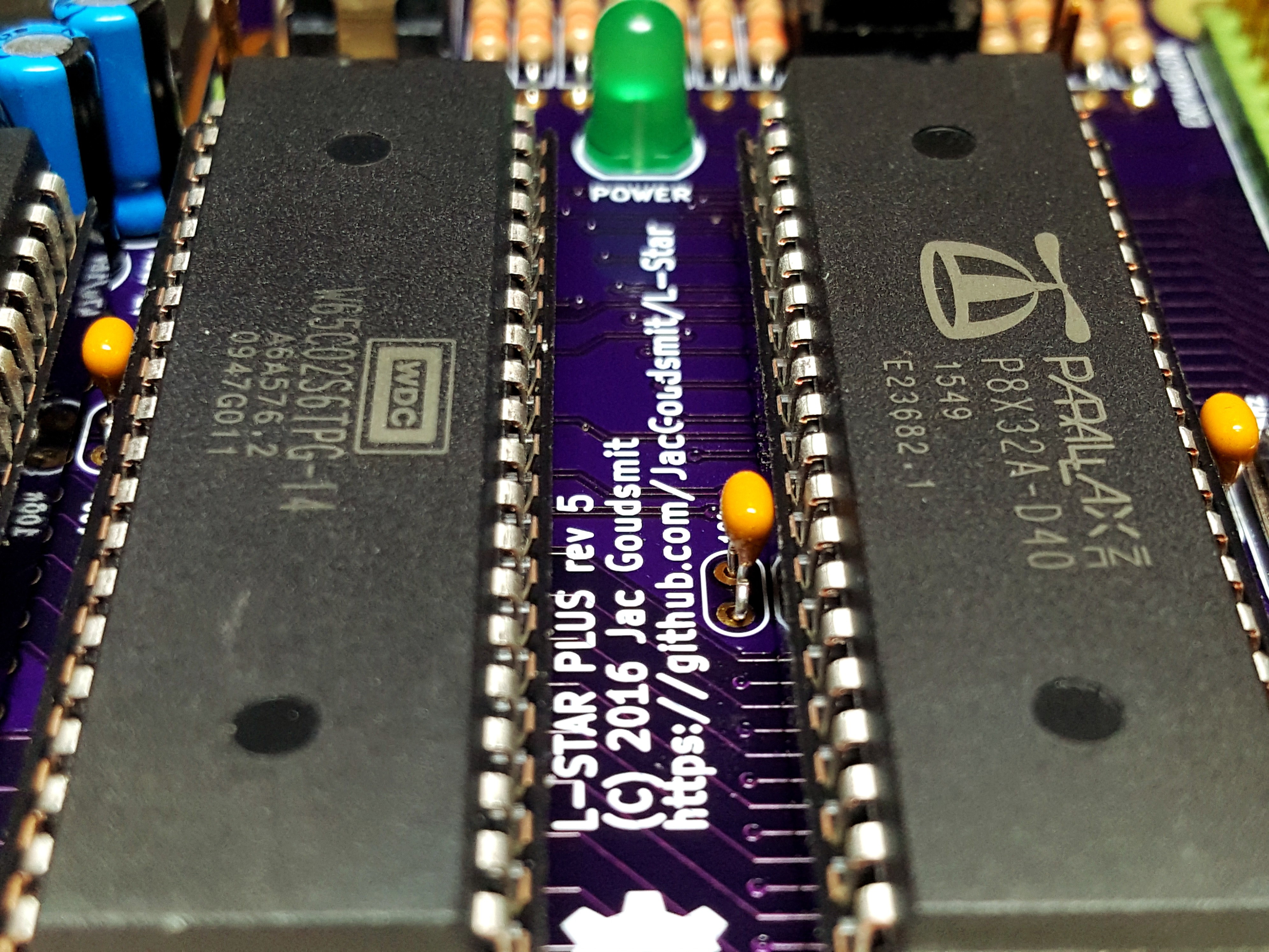
I also designed a custom PCB in Kicad. I added the 128KB SRAM chip from the Propeddle design back to it, as well as the power supply and an expansion port. I called this the L-Star Plus, and it's available on Tindie as a kit.
All the parts on the PCB are through-hole, so it's easy to solder the project together.
How it works
The most important inputs and outputs on the 6502 and 65C02 (I use the names interchangeably) are the data bus, the address bus, the R/~W (Read/Not Write) pinand the clock input.
The Propeller is connected to all those pins on the 65C02. The Propeller has eight cores called "cogs", and each cog can run its own program to interact with the 65C02. Each module is different, but all modules work from the same principles:
- Wait until the clock goes LOW. This is the start of a new 65C02 cycle.
- If the cog put any data on the data bus during the previous clock cycle, it needs to remove the data from the data bus now.
- Read the address and the R/~W pin.
- Analyze the address and the R/~W value and determine if it's necessary to take any action. Some modules compare the address to known values and jump to the appropriate code; some modules simply look up the address in a table and do an indirect jump.
- Wait until the clock goes HIGH; this is the second half of the clock cycle.
- If the R/~W pin is LOW, the 65C02 now puts a byte of data on the data bus. If necessary, the cog program reads it and takes action depending on what its function is.
- If the R/~W pin was/is HIGH, the 65C02 is in Read mode. If the address is of interest to the program, the Propeller has to figure out what data to put onto the data bus, at least some time (the Read Data Setup Time) before the end of the clock cycle.
- Wait until the clock goes LOW again, like in the first cycle.
Several modules are provided in the Github archive, all of them are part of their own project. A project combines all the modules together, to either emulate an existing 6502 system or to implement an entirely new one. Here are some examples of software modules I've written so far.
"Hardware.spin" Module
Each project has a module that defines constants for all the pin numbers. This is not really technically a requirement, but it really helps to keep the pin definitions together. Basically all it contains is an enumerated declaration of constants that can be used in all the other modules without having to remember which pin has which function. There can be some slight differences between the projects, because it's possible to use jumpers to reconfigure some pins. The text of the module will make it clear how to set the jumpers. There is no code in the module, except for a dummy subroutine without which the Propeller tool will generate an error message.
"Clock.spin" Module
The Propeller generates the clock for the 65C02 by using a numerically controlled oscillator (NCO). The Western Design Center version of the 65C02 is a static design, so the clock can be stopped and restarted at any time. The WDC 65C02 can run at up to 14MHz but the Propeller isn't fast enough to keep up with it when it runs that fast. The maximum 65C02 speed supported by the L-Star project and its modules is 1MHz.
Because of all the Propeller pins that are in use to monitor the 65C02, there aren't many pins left. The clock input of the 65C02 is the same pin as the one that's used to clock the I2C EEPROM that holds the firmware. This is okay: the 65C02 will get a number of clocks while the Propeller is booting and loading its program from the EEPROM, but the EEPROM won't interfere with operation as long as the Propeller keeps the SDA line HIGH during normal operation. The clock module takes care of setting up the NCO, declaring the necessary pins as outputs and starting the clock when necessary.
Unlike the other modules mentioned here, the clock module doesn't need any Assembly code. It just contains a few reusable Spin subroutines that take care of business.
"Memory.spin" Module
The memory cog is capable of emulating ROM and/or RAM in the system. It's even possible to run multiple memory cogs, each emulating a ROM/RAM memory area to the 65C02.
The code in this module was written in such a way that a block of RAM in the hub of the Propeller is presented to the 65C02 as a block of ROM followed by a block of RAM, where the split between ROM and RAM can be at any point in the block (so it's possible to emulate ROM only or RAM only).
The main loop of the memory cog takes the address from the 65C02 address bus and applies an offset to calculate the address in the Propeller hub RAM that represents it. Then it compares the result against the known borders:
- Start of ROM
- End of ROM / Start of RAM
- End of RAM
If the address is out of range, nothing happens.
If the 65C02 is writing and the address is between the start of RAM and the end of RAM, the code waits for the second half of the clock cycle, which is when the 65C02 puts data on the data bus. Then it reads the data bus and writes the value to the hub.
If the 65C02 is reading and the address is between the start of ROM and the end of RAM, the code reads a byte from the hub at the calculated location, and puts it onto the data bus.
After these operations, the cog waits for the end of the clock cycle and starts the process again from scratch.
It's possible to map the hub memory anywhere in the 65C02 address space. This is convenient, because all 6502 computers need a ROM area at the end of their address range (because that's where the reset and interrupt vectors are stored) and RAM at the beginning (because that's where the zero page and stack are). The Memory cog code does a "wrap-around" of addresses so that a single instance of this module can take care of the ROM at the top as well as the RAM at the bottom.
"SRAMctrl.spin" Module
The Propeller only has 32K of hub RAM, so if you want to write firmware to emulate a more complicated computer, it doesn't leave a lot of space to emulate RAM or ROM. That's when the SRAM chip comes in handy.
The SRAM chip on the L-Star Plus is connected to the data bus, address bus and R/~W line, so that it potentially covers the entire 64KB address space that the 65C02 can handle. All it takes to engage it, is for the Propeller to activate the Chip Enable (~CE) pin at the right time.
The main loop of the SRAM control cog monitors the address bus and uses a lookup table in cog memory to activate the ~CE pin of the SRAM chip. Actually there are two lookup tables: one for reading, one for writing. Each table is 128 words of 32 bits each, and each bit represents 16 addresses in 65C02 address space, so the first bit in the table represents addresses $0000 to $000F, the second bit represents $0010 to $001F, etc.
During the first half of each 65C02 clock cycle, the SRAM control cog checks the address bus value and calculates the word-offset and the bit number in the table. It checks the appropriate bit in the table to figure out if the SRAM chip should be enabled or disabled. During the second half of each clock cycle, it enables the SRAM chip by pulling the ~CE line low.
Unfortunately, the SRAM control cog uses up a cog and needs an output pin. That means that when the SRAM chip is in use, the jumpers have to be changed. If the project uses video and a keyboard, it has to use the nifty 1-pin keyboard driver that only uses the data line, not the clock line. The problem with that is that the Propeller can't send data to the keyboard (e.g. to turn the CAPS LOCK, NUM LOCK, and SCROLL LOCK lights on and off) and it has to figure out what the bit rate is by asking the user to hit the space bar on the keyboard when the system starts.
"A1PIA.spin" Module
The Apple-1 computer is very simple, and only has access to the outside world via a 6820 PIA (Peripheral Interface Adapter) chip. The Apple 1 PIA emulator module emulates this chip:
- When the 65C02 reads from address $D010, it will see the ASCII code of the last key pressed, with the Most Significant Bit (msb) set. Whenever the 65C02 reads from this location, the msb at location $D011 is reset
- When the 65C02 reads from address $D011, it reads a byte whose msb is set to 1 whenever there is a new character available from the (emulated) keyboard. The msb is reset to 0 whenever $D010 is read.
- When writing a byte to $D012, the seven Least Significant Bits are sent to the screen
- When reading a byte from $D012, the seven least significant bits are the same as the value that was last written here by the 65C02, but the msb is reset when the video character has been processed.
The PIA emulator works together with the Spin code in the main program. The main program "pumps" bytes from the Apple 1 PIA cog to the Terminal module and vice versa.
"SerKbd1TV.spin" Module
This module implements the keyboard input and text output for the Apple-1 emulators. It reads keyboard input from either the PS/2 keyboard (or the 1-pin keyboard on the Apple-1 SRAM project) or the serial port, and it writes text output to the video screen as well as the serial port.
When the L-Star is configured to run as an Apple-1 emulator, all text input and output happens one character at a time, just like on the real Apple-1: The 6502 on the original Apple-1 didn't have direct access to the memory that represents the characters on the screen, it could only add a character at the current cursor location, or send the cursor to the next line by sending a line feed. Because of this, it's pretty easy to emulate the screen and keyboard functionality of an Apple-1 with a serial port: Whenever the 65C02 sends a character to the video output port of the emulated PIA, the software on the Propeller sends the character to the serial port, and whenever the serial port on the Propeller receives a character from the computer that's attached to it, it emulates a keystroke on the PIA.
Of course we also want to be able to see the text on a real screen and type it with a real keyboard. But with so many Propeller pins in use for the address bus, data bus and other stuff, there are only 3 pins left to connect an optional PS/2 keyboard and an NTSC or PAL monitor.
The Propeller does a good job of generating video on 3 pins, but that wouldn't leave any pins at all for the keyboard or to control the RAM chip. So instead of using one of the standard 3-pin video drivers, I used the "1-pin TV driver" from the Parallax Object Exchange (OBEX). For the keyboard I used the regular PS/2 driver in the non-SRAM Apple 1 project, and the 1-pin keyboard driver for the SRAM Apple 1 project.
The 1-pin TV output may not work for everyone, because it's sort of non-standard. The 1-pin keyboard also has its disadvantages, for example you have to let the module calibrate its timing by pressing the space bar before it can be used. But the serial port is needed anyway to download the firmware into the Propeller, so you can do without the video output and keyboard input if you want to build the minimal version of L-Star: just use the serial port. The serial port settings are 115200 bps, 8 bits per character, 1 stopbit, no parity, no handshaking.
"OSIkeyboard.spin"
Besides the Apple-1, another computer that can be emulated is the OSI Superboard II, also known as the OSI Challenger, also known as the UK101.
The video hardware on the original OSI computer was very simple: the screen used 1KB of memory to display a text-only screen, and the CPU had direct access to that memory. The font that the OSI video adapter used, had 256 glyphs so I had to modify the 1-pin TV driver because it normally only supports 128 glyphs and a reversed video mode. The original 1-pin TV driver stored the font in cog memory, but this isn't possible with a 256-character font because it would leave no space for the code that generates the signal. So I modified the code to use hub memory instead of cog memory to read font data (as well as the video buffer of course). I made this module for Vince Briel's "Superboard III" project and reused it in my own project.
The keyboard module was more difficult. The problem with the keyboard was that on the original OSI hardware, the keyboard is a matrix of switches, which gets read and decoded by the CPU, whereas a PS/2 keyboard has a microcontroller built in that does the work of decoding the matrix. The OSI keyboard module in the L-Star project was derived from Chip Gracey's PS/2 keyboard module but instead of decoding the key strokes to ASCII codes, it controls a small array of bytes in the hub. Each byte represents a row of the keyboard, and each bit represents a key on the OSI keyboard being pressed (1) or not (0).
A second cog in the keyboard module monitors the 65C02 bus to check if it accesses the keyboard's location. Whenever the 65C02 writes to the location, it selects the active keyboard row and whenever it reads from the location, it reads the byte that represents the keys that are pressed for that row. There's a small problem with this: in theory it's possible to let the 65C02 select multiple rows on the original hardware, and check if any key on any of those selected rows is pressed. This is difficult to emulate because the Propeller doesn't have enough time to "OR" the necessary rows together. So instead, it always pretends that only the most significant '1' bit is set.