 Jac Goudsmit
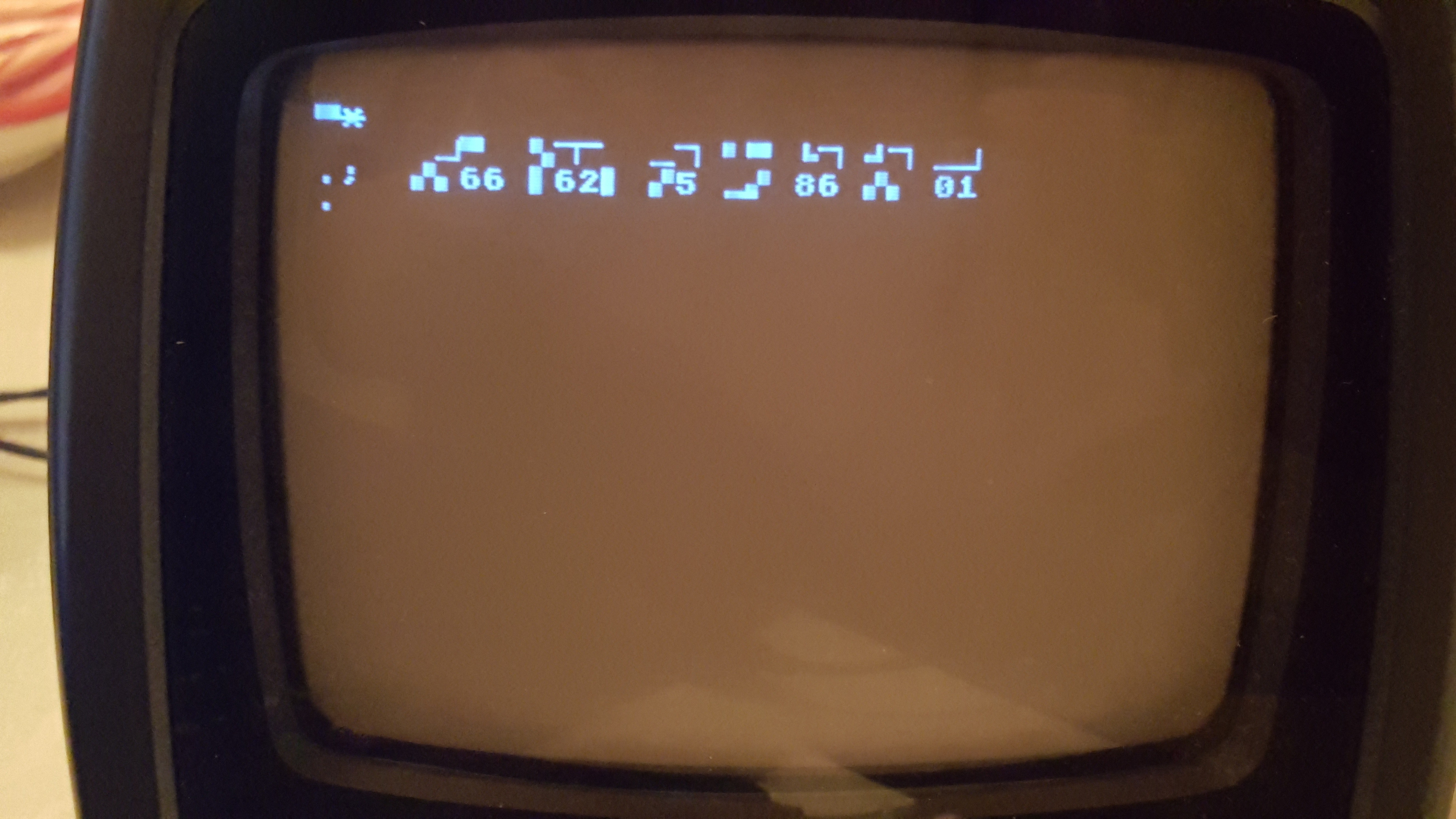 If you've followed me long enough, you know that my original purpose for the #Propeddle: Software-Defined 6502 Computer project was to build a replica of the Commodore PET-2001 and CBM series computers. The PET-2001 was the first computer I ever used, when I was about 11 years old in 1978. And now I've finally made a start on writing a software-defined computer project to emulate the PET/CBM on L-Star. As you can see in the picture, I have a long way to go.
The early PET/CBM machines had up to 32KB RAM on board, a character-based memory-mapped video display, 8KB ROM for Microsoft BASIC, 2K ROM for the screen-based editor, and 4KB for the operating system which Commodore called the "Kernal". There were 3 simple I/O chips in the early models: one for the keyboard and the cassette interface, one for the IEEE-488 (GPIB) interface, and one for the second cassette port and the user port. Later models added a CRT controller chip to simplify the video hardware.
RAM and ROM
In the projects that I've already written for L-Star, I've extensively used the Memory module which give the 6502 access to a memory area in the hub of the Propeller. To emulate a ROM, all I need to do in Spin is to put a "file" command in the source code to load a ROM image file and then run a Memory module to map it into 6502 address space. I can do this with RAM too, but the Propeller only has 32KB of hub memory available, part of which is used up by the program. Though it would be possible, in theory, to use hub RAM as 6502 RAM for the PET/CBM project, it's much easier to just use an external SRAM chip such as the one that's on the L-Star Plus board. One cog is in control of enabling the SRAM based on the address bus of the 6502, and because I already had that module, it was a matter of copying it and adding lines to initialize the module and start it up.
Video
In the original machines, video was the most complicated part of the hardware, because the RAM needs to be accessible by the 6502 while it's generating a constant signal. Just like in many other early 6502 computers, the entire system was built around the video hardware. Commodore figured out that with 40 characters per row, and a video line time of about 64 microseconds, it would be possible to run the CPU at about 1MHz and design some circuitry that alternates the access to the video hardware between the CPU and the video generator hardware twice per clock cycle. On the later 80-column motherboards, they used an even smarter approach where the video hardware sees the memory as 2048 words of 16 bits and decodes the characters at twice the speed.
With L-Star, the video part is easy because it basically has already been done. The Propeller is really good at generating video; it has I/O registers and assembly instructions to help with this. It can do 6-bit VGA or PAL or NTSC composite video, but all those modes need 3 or 4 or 8 pins. L-Star doesn't have that many pins available (most pins are connected to the 65C02) so I use the 1-pin TV driver which is fine for a monochrome text video output similar the PET/CBM. That software module wasn't written by me but by a couple of smart guys in the Parallax forums. I only had to convert the PETSCII font from a ROM dump at ftp.zimmers.net to the correct format for the 1-pin TV driver.
There are actually two fonts in a PET/CBM: one that has upper and lower case characters, and one that has upper case and graphics. And there are actually differences between the fonts in the PET and the fonts in the later CBM machines. But my short term goal was to get text on the screen, and fortunately that's just a few lines of code to start the video cog. And then another line of code to start another Memory module to give the 6502 access to the hub memory that represents the characters on the screen.
IEEE-488/GPIB
The PET/CBM talked to peripherals via a parallel interface using a standard called IEEE-488. That standard is more generally known as the Hewlett-Packard General Purpose Interface Bus (HP-GPIB or simply GPIB) and is still in use in instrumentation devices today. It made it possible for the Commodore engineers to design a computer and not worry about what kind of peripherals might one day be available for it. Commodore floppy drives (and printers and hard disks) are computers too (some floppy drives even have two CPU's), and they talk to the IEEE-488 bus via a standard protocol.
I probably won't implement emulation for the IEEE-488 bus. As far as I understand, real PET/CBMs work fine without the PIA chip that is used for the IEEE-488 interface, and there are probably better ways to load and save software and data into and out of memory. And if you want to connect L-Star to a real floppy drive, you'll have to build hardware anyway, so the need to add a PIA (and an address decoder) is probably not a big deal.
Keyboard and Cassette
PET/CBM's have two cassette interfaces, but most people only used one of them (professional users probably used a floppy drive and no tape at all). As mentioned before, there are probably better ways to get software and data in and out, so I don't think I'll write code to emulate the cassette, at least not for now. It would be nice to use the serial port (P30 and P31) on the Propeller, but I may run into trouble with that; I'll get back to this in a few minutes.
The keyboard that was used on the PET/CBM was a matrix keyboard on two ports of a PIA chip (a different one from the IEEE-488 interface). I wrote a driver for a matrix keyboard in the OSI Superboard emulator, and I'll probably modify that for the PET project. I may have to do a bit of a start-over because I'll have to use the 1-pin keyboard driver and the OSI keyboard uses 2 pins.
Tricky I/O
If you're somewhat familiar with other L-Star projects, you'll know that it has 3 uncommitted pins on the Propeller, which aren't connected to anything except the expansion header and the jumper bed. And if you counted along with the story above, you will have concluded that one pin is needed for video, one to control the SRAM chip and one to get input from a PS/2 keyboard. That means all pins are in use.
This is a problem, because there is one feature that I haven't mentioned yet: in the PET/CBM, the IRQ line is activated sixty or fifty times per second, depending on the mains frequency (I think the signal actually comes from the video circuitry but that doesn't matter). This is used to time operations in programs, let the cursor blink, etc. And there's no pin free on the Propeller to generate the signal that's supposed to go to the IRQ line of the 6502.
I'm not sure yet how to solve this. I could use P30 (which is normally used for serial transmit) to connect to !IRQ. That makes it difficult or impossible to use the serial port while the emulation is running, unless I write some software to implement a 1-pin serial port.
Another possibility is to not implement a keyboard emulator for the PS/2 keyboard, so it frees up a pin that can be used for !IRQ. But that makes it necessary to connect a computer to the serial port to generate keyboard input. Also not a very good solution; I'd like to the design to be stand-alone.
I could also try to do something in software: fifty or sixty times per second, I could let the Propeller feed a BRK instruction to the 6502 which is executed pretty much the same as an IRQ interrupt. But a normal IRQ doesn't set the B flag in the flags register whereas the BRK instruction does. So the Propeller will also have to interfere when the 6502 pushes the flags onto the stack, or when it accesses the location on the stack where they are stored. That could become very complicated. Which is somewhat ironic because in the real computer, the circuit that generates the interrupt is so very simple.
So About These First Life-Signs?
In the picture above, you see what appeared on the screen when I emulated just the RAM (with the SRAM module), the video, and the ROM. No peripheral chips are emulated yet. What I would expect on the screen is a message "COMMODORE BASIC" and "31743 BYTES FREE". But it looks like the execution drops into the machine language monitor as if it executed a BRK instruction. I suspect that the behavior is caused by a wrong combination of ROM image files. I started on the PET project about 2 years ago and hit a snag; I don't remember what it was but it wouldn't put anything on the screen at all. The project got shelved but now I picked it up and made some tweaks and write a module to trace the 6502 to follow what it's doing. I know I experimented with various combinations of ROMs when I worked on it before, so maybe what's in there is not correct, and somewhere somehow the code in one ROM jumps or calls code in another ROM that's not in the location where it's supposed to be.
What worries me more is that the display is garbled: That means that the 6502 is writing data to emulated screen memory but there are some bits that are mangled. I have a feeling the RAM chip is holding the databus a little bit too long at the end of a clock cycle, so I may have to tweak the Propeller code a little. The 6502 has to execute a lot of code and read and write a lot of locations in ROM and RAM to get to the point where it displays the Machine Language Monitor prompt, so I'm optimistic that it's fixable.
Discussions
Become a Hackaday.io Member
Create an account to leave a comment. Already have an account? Log In.
Couldn't you put add a 555 timer or a 12F series PIC for the IRQ on the expansion bus? Perhaps a PIA or 2 as well?
Are you sure? yes | no
Yes, and I may do one or all of those in the future :-)
Are you sure? yes | no