-
SRAM Chip Control Cog
05/29/2016 at 06:36 • 0 commentsThe Apple-1 and OSI Superboard / Challenger emulators don't need a lot of RAM and ROM memory. For those projects, the Memory cog module (see the project details) does its task just fine to map a ROM image into the 6502's address space, and let the 6502 (effectively) read and write the Propeller hub memory as if it's real RAM.
But the Propeller only has 32KB of hub memory, and for some (future) projects, that simply might not be enough, and it will be necessary to put some real memory in the system.
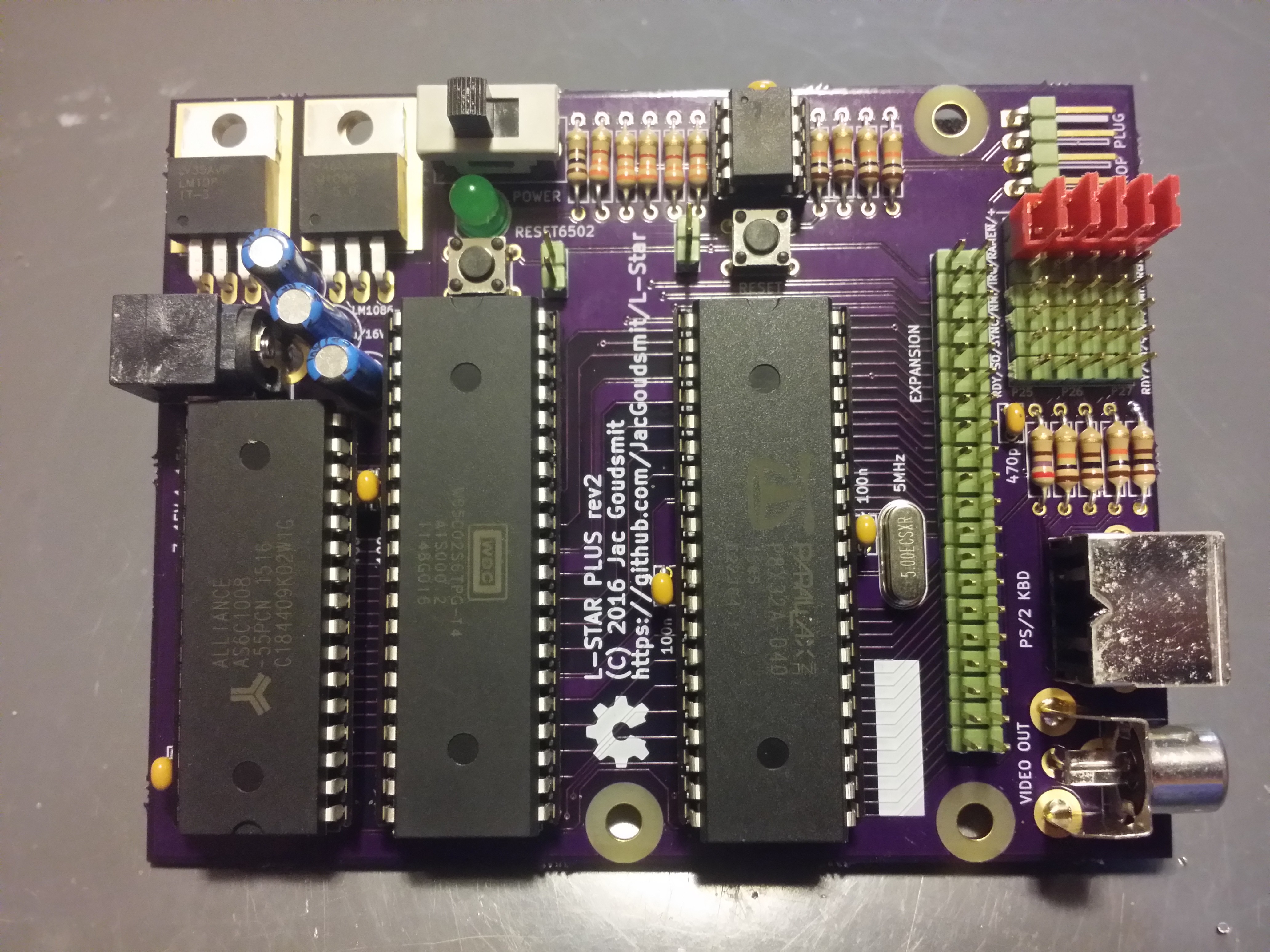
I designed the L-Star Plus as a kit that includes an SRAM chip to take care of this problem. The chip is a 128KB Alliance Memory AS6C1008-55PCN. Why 128KB you might ask, if the 6502 only has 64KB of address space? Well, as it turns out, there is no 64KB SRAM chip, at least not one in a DIP package, with 16 address lines and 8 data lines, and 3.3V compatibility. So I had to use a 128KB chip instead. First world problems!
The lowest 16 address lines of the SRAM are connected to the 6502 address bus, and the data lines are connected to the data bus. The highest address bus pin (A16) was grounded in the Rev.1 PCB design, but is available on the jumper block on the L-Star Plus in the Rev.2 design.
That means that the Propeller can be connected to the SRAM chip's Chip-Enable-Not pin (~CE) to put the chip on the data bus when needed. All that's needed is a new software module that I wrote last week, called SRAMctrl. This module builds a literal bitmap of which addresses in the 6502 address bus should be mapped into the SRAM chip. Then, on each 6502 clock cycle, it checks the bit in cog memory that represents the address that the 6502 requests, and, if necessary, activates the SRAM chip's Chip Enable line.
The bitmap actually consists of two tables that seamlessly work together. The R/~W line of the 6502 address bus is used as an extra address line when an index into the table is calculated (it's not a coincidence that the R/~W line is connected to the P24 pin of the Propeller, adjacent to P23 where address bus line A15 is connected). That way, reads and writes can be controlled separately and it's possible to create read-only memory areas in the SRAM chip. For some future large projects, this may make it possible to let the Propeller initialize the RAM with a ROM image file, and then let the 6502 boot from the SRAM. See if you can do that in an ordinary 6502 system (tip: you can't).
It would be nice if each address on the 6502 address bus were represented by one bit in the table, but this would be difficult. The table wouldn't fit in a cog, so I would have to e.g. let two or more cogs work together or retrieve data from the hub. Using two or more cogs just to turn an SRAM chip on or off is not very efficient, and putting the data in the hub is a non-starter because it takes quite a few Assembly instructions to generate the index into the table, shift the bit out from the long-word entry. If I would have to add a hub access instruction to that, there just wouldn't be enough time in a 6502 clock cycle to get everything done.
So the compromise is that (for now), each bit in the table represents 16 bytes in 6502 address space: the first bit represents addresses $0000 to $000F, the second bit represents $0010 to $001F etc. For most uses, this should be more than adequate. A future version of the SRAM control cog could be made to support a one-in-8 resolution instead of the current one-in-16 resolution, by eliminating the separate handling of reads and writes.
Another compromise is that if you want to use the SRAM chip in your Software Defined Computer, you'll have to either give up the monochrome 1-pin video output, or you'll have to switch from the full PS/2 keyboard driver to the 1-pin keyboard driver (by Ray Rodrick a.k.a. Cluso99 on the Parallax forums) which doesn't need the keyboard clock input. For now, that also means that you'll have to ask the user to push the space bar on the PS/2 keyboard to measure the keyboard-specific clock speed. But I'm thinking it should be possible to do away with that, with some smart programming.
The SRAM control cog is in a module called SRAMctrl.spin in the new Apple1SRAM project. The code in that project activates the SRAM for the entire low 32K memory area which is also present in Vince Briel's Replica 1. It doesn't use the memory cog to emulate any RAM, only ROM. The 32K of available RAM is nice, because now there's no need to patch the Krusader program in the emulated ROM (it's kinda hard coded to expect that the system has 32K). It's trivial to make the amount of SRAM even larger, but instead of mapping more SRAM into memory, I wonder if maybe I could emulate the CFFA1, or the Apple 1 cassette interface using the Propeller. That would make L-Star into a Replica 1 Replica! :-)
-
Hardware Revision 2
05/16/2016 at 23:39 • 2 commentsThe L-Star project has been getting some attention recently, so I decided to do some work on the hardware.
I added a couple of missing pull-up resistors, so that the circuit keeps working correctly, even if you remove the Prop Plug from it. I also made the footprint for resistors a little bigger so that common carbon film resistors fit nicely. And I added an On/Off switch so you can turn the system off and don't have to go searching for the power cable that fell down behind your desk when you want to power it up again.
Even though there are more components and all the resistors take up more space, it was still possible to reduce the board size significantly. I didn't quite get it down to the "magic" 80x100mm Half Euro-card size, but I got pretty close: the Rev. 2 board is 12% smaller (in surface area) than the Rev. 1 board.
I ordered a set of boards from OSHPark, and created a shared project on the OSHPark website too. I also created a project at Mouser. The result looked somewhat like this.
![]()
Update: Hold the Phone!
Unfortunately once I got the PCB's back from OSHpark and put it together, I noticed that I had made a few small but annoying mistakes.
For one thing, I added the A16 address line for the 128KB SRAM chip to the jumper block, but I added it to the wrong jumper. That means with the Rev.2 PCB, it's not possible to connect the ~RAMEN line to P27 with a jumper, and that really really REALLY is the pin I would like to connect it to.
Another problem: The smaller board size made it cheaper to produce, but with the added on-off switch, the components are so close together that I have trouble pushing the reset button for the 65C02. My finger just doesn't fit between the LED, the chip and the 2-pin header to reach the button.
So the bad news is that I'm going to have to design a third version of the PCB, even though the first two versions technically work just fine. I guess the good news is that I didn't make a production run of the Rev.2 board. And I have a chance to fix another thing that's been nagging me for a while: the solder islands were too small. More news soon!
-
Ohio Scientific C1P / CompuKit UK101 Replica
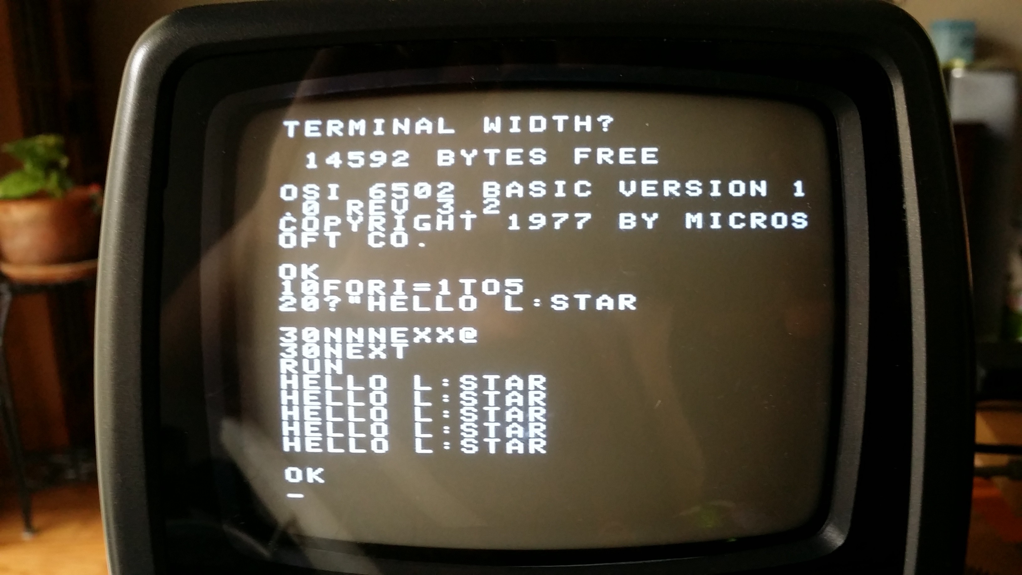
01/19/2015 at 06:02 • 0 commentsOhio Scientific (OSI) was a company that produced many 6502-based computers in the late 1970s and early 1980s. One of those computers was the Superboard II, also available in a case as the Challenger C1P. In the UK, many people may remember the CompuKit UK101 which was a clone of the Superboard II, available as a kit from a magazine. The Superboard II doesn't use IRQ or NMI interrupts, generates character-based monochrome video, and the original machine only had 4KB of memory. This makes it a great candidate to be replicated on the L-Star hardware.
![]()
As I may have mentioned before, I worked with Vince Briel at Brielcomputers.com on a replica of the Superboard II last year, so I had some code laying around from that project: a modified 1-pin TV driver that can handle the 256-character OSI font, and an OSI keyboard emulator.
The Propeller has 32 digital I/O pins, of which 25 are used by the address bus, data bus and R/~W line. Two pins are more or less reserved by the serial connection to the PC and two are used by the I2C EEPROM that stores the Propeller program (the 6502 clock is generated on the I2C clock line). That leaves only 3 pins for other I/O. Two are used for the PS/2 keyboard, and one is used for video.
One Pin TV Driver
You may wonder how the Propeller can generate an analog video signal on a single digital pin. The secret is that it uses one of the built-in timers to generate a high-frequency block wave. The impedance and capacitance of the connected monitor reduces the high-frequency signal into a DC-level, which is interpreted as black. The Propeller sets the pin LOW for blanking and synchronization, and it sets it HIGH for white.
The 1-pin TV driver was written by a few members of the Propeller forums as a means for debugging programs, but originally, it was written in such a way that it wouldn't have worked for the Superboard II emulator. For one thing: it stored the font in the cog, which made it incapable of displaying the 256-character OSI font: the font data would have taken up the entire cog, not leaving any memory space for the code. So I modified the code to read the font from the hub. This reduces the maximum resolution a bit (hub access is much slower than cog access), but we should never need more than 64 characters per line, which is well within the limits of the modified driver.
The original Superboard II video hardware was a very simple circuit. It generated 32x32 characters (totaling 1KB of video memory) of monochrome video at 60Hz (50Hz in Europe). But the characters around the edge would be in the non-visible areas of most screens, so the software only used 25 lines of 25 characters in the middle of the screen. I modified the 1-pin TV driver so that the first character that's displayed doesn't necessarily have to be the first character in the video buffer. And at the end of each row of characters, the driver adds a number to an address, to make a few characters invisible. That way, the line addresses are still (say) 32 addresses apart, but only (say) 25 characters per line are visible.
For now, the 1-pin TV driver is hardcoded to emulate the Superboard II display with the 1KB memory (32x32 characters). The parameters can easily be changed to change the video to 48x32 or even 64x32. Some of the original video adapters for other OSI computers were capable of switching between two modes (e.g. 32x32 and 64x32) by writing to a specific address in memory; this is currently not possible because the video parameters are calculated at compile time; however I'm planning on changing this in the future.
OSI Keyboard Driver
All computer keyboards are implemented as a matrix of switches: Each key is connected to one row and one column of electric lines. The computer activates a row, and then checks which column(s) is/are active to see which key switch connects that row to a column. In modern computers and in your PS/2 keyboard, the computer that takes care of scanning the keys has been replaced by a microcontroller. Simply said, the microcontroller in a PS/2 keyboard translates the scanned keys to a serial signal, which is sent to the host computer (the host computer can also send signals to the keyboard to turn the LEDs on or off).
But in old computers such as the OSI Superboard II, the computer was directly connected to the keyboard matrix, Obviously this has disadvantages: the computer won't see a key press if it doesn't scan the matrix every once in a while. We may not be able to change that, but we do have to translate the data from the PS/2 keyboard into scan data.
On the Superboard II, the 6502 stores a value to location $DF00 to activate the rows of the keyboard matrix, then it reads back from the same location to find out which column(s) on that row have their switches pushed down. It's possible (to an extent) to detect multiple simultaneous key presses, and the keyboard matrix on the Superboard II was especially designed to make sure that simultaneous pressing of the shift, shift-lock and repeat keys together with other keys would never be a problem.
The OSI keyboard driver has to do the reverse of what the controller in the PS/2 keyboard already does: it has to convert the incoming serial data from the keyboard back to a keyboard matrix that the software will understand. The work to do that is divided between two cogs: the first cog executes pretty much the same code as the original PS/2 driver included with the Propeller software, the second cog monitors the 6502 address bus and data bus to check if any keyboard scanning is going on.
Instead of generating an ASCII code or a scan code, the first keyboard cog keeps track of a table of which keys are currently pressed. The PS/2 protocol allows multiple keys to be pressed at the same time (not all keyboards support this equally well but that's a different problem) so the cog can simulate simultaneous pressing of keys. The table matches the keyboard matrix of the original OSI, and stores a bit value of 1 for each key that's currently pressed. When the second cog detects that the 6502 is scanning the keyboard by writing a value to $DF00, it basically changes the index of the byte in the table that Propeller will present to the 6502 when it does a read from $DF00.
The value that the 65C02 stores at address $DF00 can't be used directly. There are 256 possible values of the byte that the 65C02 may store at the location, but there are only 8 rows. On the real hardware, it would be possible in theory to activate multiple columns at once, but if we would emulate this, it would take a lot of extra code, and/or a lot of extra memory. Instead, the driver implements a compromise: as long as the 65C02 only scans one row at a time, it will get accurate results, but if it tries to scan multiple rows at the same time, it gets the columns for the row with the highest number. To accomplish this, the Propeller code uses a table that it generates at runtime, containing the base-2 log values for values 1 to 255.
ACIAThe cassette port of the Superboard II was connected via a Motorola 6850 ACIA (serial port controller). At this time, that chip isn't emulated yet. I will fix that soon: the serial port to the PC can then be used with a terminal program to save or load programs.
-
Breadboard Time
01/19/2015 at 02:01 • 0 commentsCreate an Apple-1 replica without any soldering? Yes it's possible!
![]()
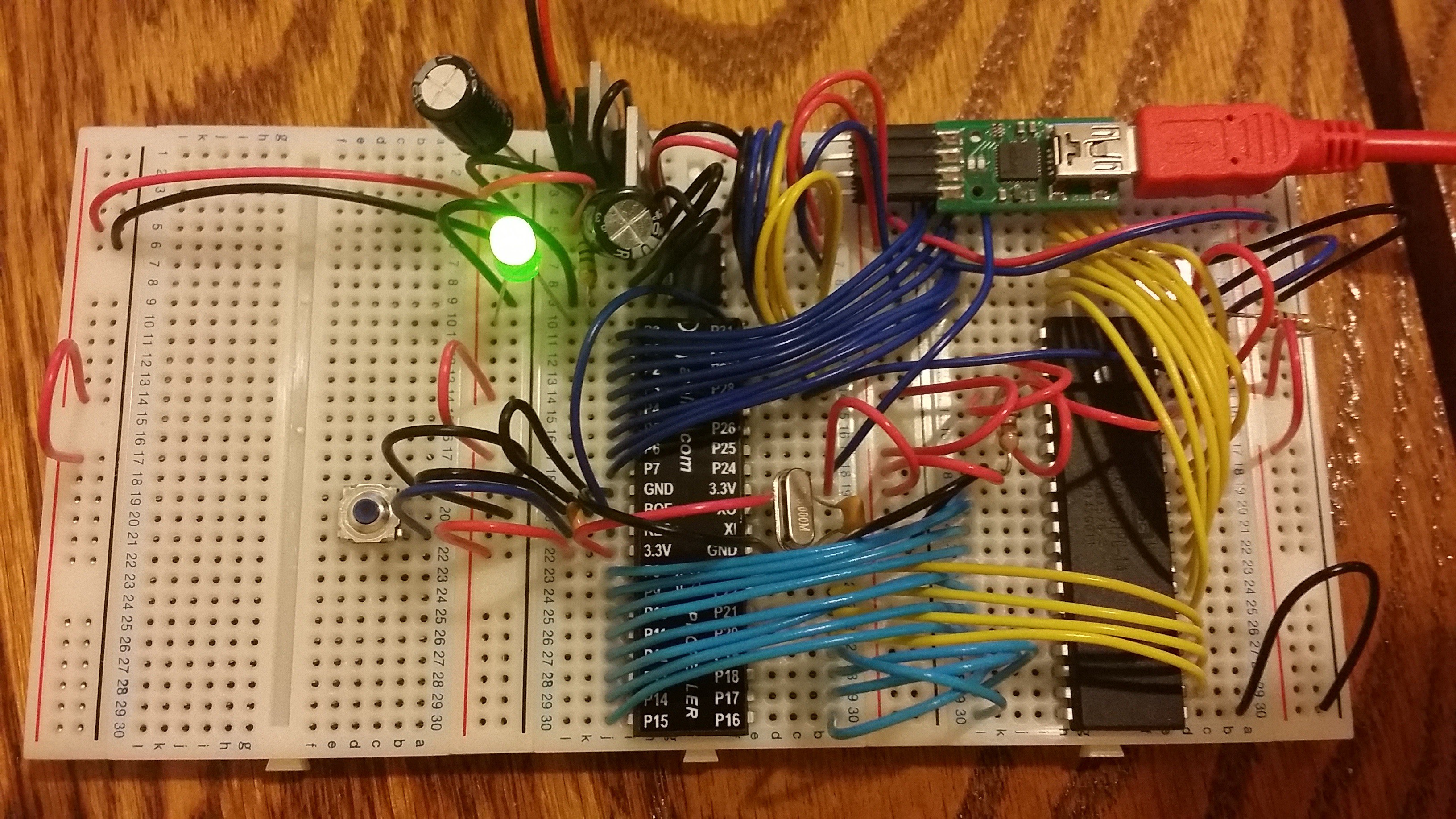
When I went on a business trip in December 2014, I took my L-Star project with me to work on it from the hotel. Unfortunately it didn't survive the trip: The Propeller stopped responding to the PC.
![]()
The light was on, but nobody was home.
![]()
Because I was away from home, I didn't have the tools or parts to check what was wrong. Ironically, I was near the Parallax office in Rocklin, California, but getting parts from there wasn't going to do me any good because I didn't have the tools to put a replacement together either.
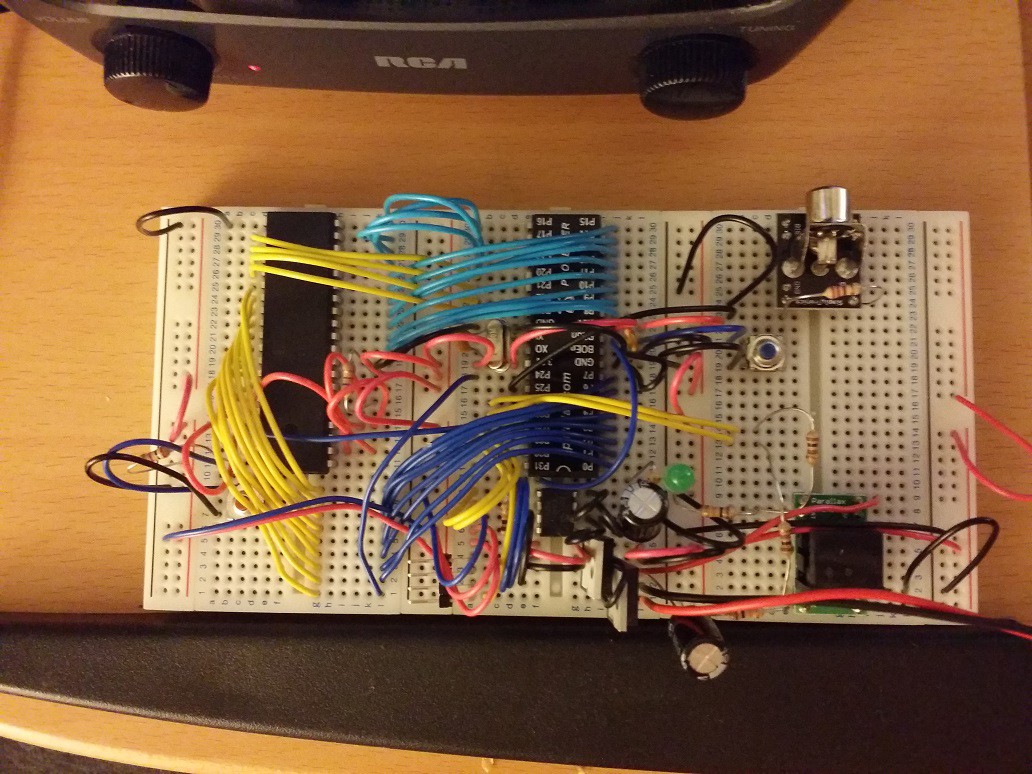
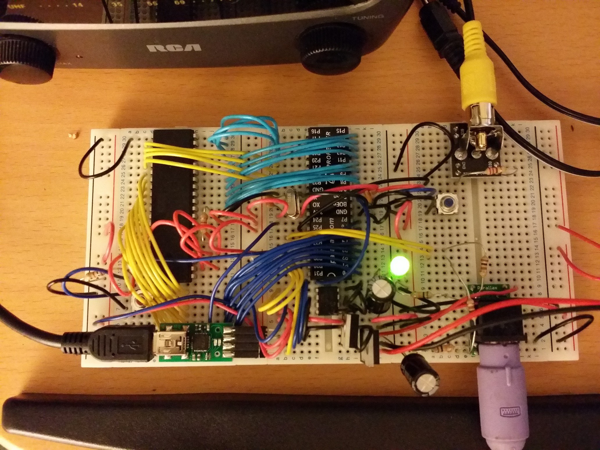
So my only option was to get the Propeller Education Kit (short PEKit) from Fry's Electronics in Sacramento, and use it to rebuild the L-Star project on a breadboard. This was the result.
![]()
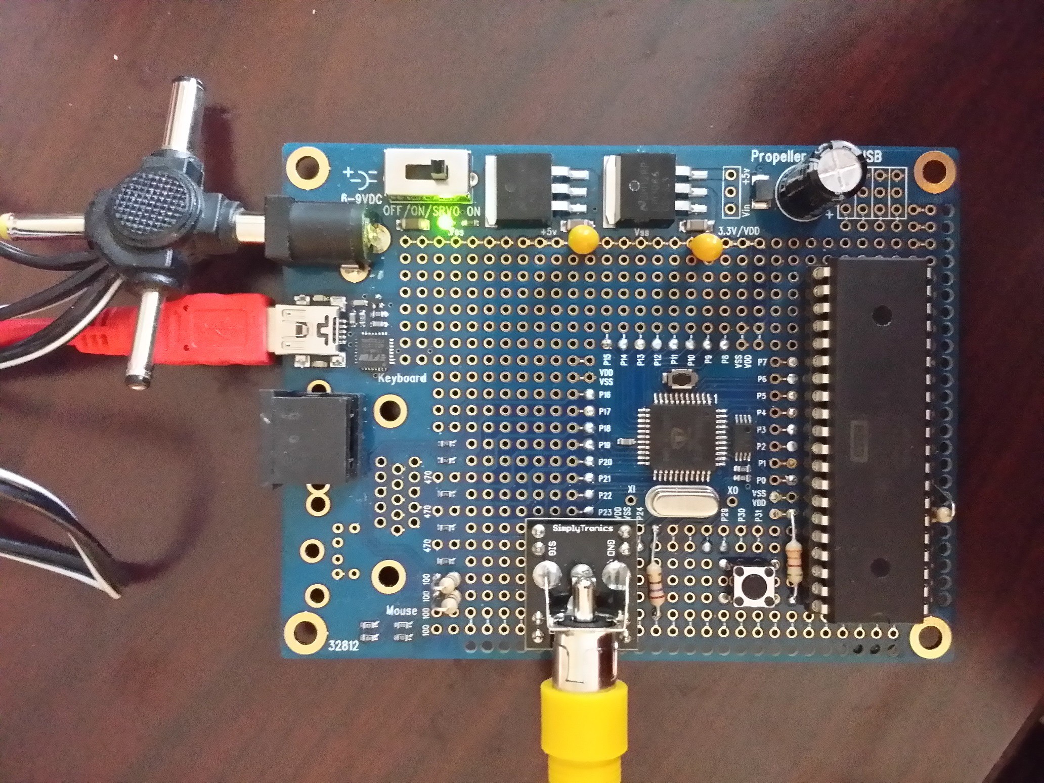
The PEKit is a great set of breadboards, parts and wires (not to mention the great book by Andy Lindsay that's included), and it was fun to set it up. All that was missing was the WDC 65C02 (which I got from the socket of the original build), a power supply (the PEKit runs on a 9V battery) and breadboard connectors for video and the PS/2 keyboard connector. Well, as it happened, I had ordered those from Parallax just before I left on my trip, so when I got home I could fix that problem.
![]()
Next mission: a replica for the OSI Superboard.
L-Star: Software-Defined 6502 Computer
Replicate an Apple-1. Or an OSI Challenger. Or something else. Design your own 6502 computer by programming it.
 Jac Goudsmit