 John Sully
I've been spending some time thinking about my implementation of the ternary full adder. This website has been very helpful with working out the design but I was discouraged with the large number of gates involved. My initial estimates were somewhere in the order of 30+ transistors per trit, which would ultimately make the whole adder close to 200 transistors. Constructing this with discrete components would be very tedious so I wanted to see if I could economize somewhat.
Theory of the Carry Function
I started out by taking a closer look at the carry function. The inputs to the carry function are the previous carry, and the bits of our two operands. Looking at the truth table I noticed it could be easily simplified:
++0 = +carry, --0 = -carry
+++ = +carry, --- = -carry
++- = 0carry, --+ = 0carry
00X = 0carry
This property holds for all permutations. In English the function for the carry is: of the 3 inputs at least two must agree, and none may dissent.
An Idea
Normally you would construct this with a combination of gates, but I started to wonder if I could build a circuit where the dissenter would "pull down" (or up), the sum to something close enough to zero that the output transistors would turn off. Essentially doing some of the computation in an analogue circuit.
The design I came up with is a passive mixing circuit feeding into a ternary NOT gate which acts as our output buffer. This computes the inverse of the carry function but another NOT gate on the output would easily correct that. With the passive mixer each input's voltage is effectively divided by a third and summed with the others. So assuming +/-5 signalling: +5, +5, +5 inputs sum to: 5/3 + 5/3 + 5/3 = 5.
An interesting thing happens when they start to diverge though:
5/3 + 5/3 + 0/3 = 3.33V
5/3 + 0/3 + 0/3 = 1.66V
5/3 + 5/3 + -5/3 = 1.66V
That 1.66V is important. With ideal MOSFETs that 1.66V would be treated as positive by the gate. But real MOSFET transistors are not linear, they usually have some initial resistance and don't start reacting until around 2 or more volts. That means our 1.66V will be effectively rounded down to zero giving us the output we need.
Implementation
Given that we can design and simulate the circuit in LT-SPICE:
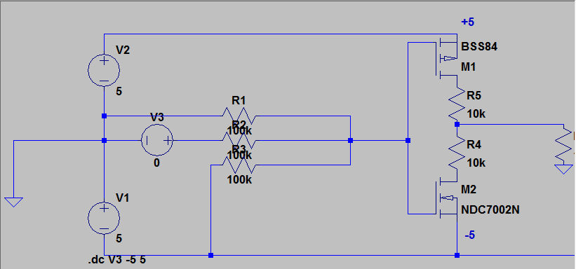
The left of R1, R2, R3 are the inputs to our logic gate. For the simulation R1 is wired to logic 0, R3 to -5V, and R2 to our voltage source V3. Sweeping V3 from -5 to +5 volts we get the following output:
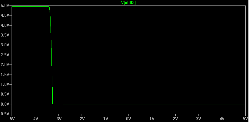
We can see on the left that as R1, and R3 are both at -5V they are "agreeing". The output is +5 volts due to the inverter used as our output stage. Another inverter would return this to the correct -5 volts. As V3 sweeps closer to logic zero and "abstains" just as R1 is doing; we no longer have enough voltage into M1 and as the transistor turns off it quickly reaches equilibrium with M2 keeping the output at 0 volts - just as we want. As V3 progresses to +5V it effectively cancels out R3 giving a true 0V to our inverter and we remain at 0 volts for the output.
The graph is nearly perfectly mirrored when simulating with positive R3 at +5 volts.
Drawbacks
This design is not without its downsides. Ideally you'd like your gates to have infinite input impedence and zero output impedence. The passive mixer drastically lowers our input impedence to near 100K. This combined with the already high output impedance of our inverter circuit means this gate will be hard to drive. This will likely have a negative impact on the speed we'll be able to operate this gate at, as well as waste power. This also puts constraints on the voltage our logic can operate at. A 5V range with +2.5/-2.5 is not high enough to reliably overcome the threshold of our transistors so we need a rather high 10V range of +5/-5. This large range will be more difficult for our transistors to drive.
Conclusions
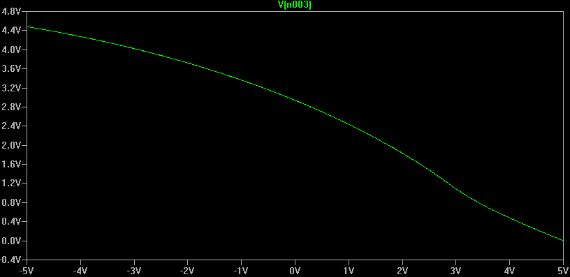
It's important to realize that this only works because we're working with non-ideal transistors. When I first simulated this design using ideal transistors it did not work correctly. This is a pleasant turn of events as normally the non-ideal nature is a significant problem to be worked around. While this gate would never be used in high performance integrated circuits due to the drawbacks mentioned it is very economical. This is exactly what we want when we're building a computer by hand with discrete transistors. If we wanted raw speed we'd be using an FPGA.
Just for fun, the circuit with ideal transistors:
Discussions
Become a Hackaday.io Member
Create an account to leave a comment. Already have an account? Log In.