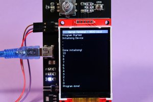
• Struggling with shift registers

    PointyOintment12/30/2014 at 08:54 0 comments

    I've got four 74HC595s on a breadboard, and I'm trying to get them to drive the 14-segment display. All I've gotten so far, though, is garbage data going through them. At first, I couldn't get them to accept data at all. Then, for some reason, they started accepting data, but nothing was displayed. I eventually figured out that this was because the display is common cathode, and I'd hooked it up as common anode—I thought I'd tried it earlier as common cathode and discovered it was really common anode, but I guess I didn't. Anyway, it sometimes lights up random-seeming segments now, if I'm lucky. The procedure I'm following is to either clock in bits using the buttons on the breadboard or use shiftOut() on my Arduino, then press the latch button, then press each /OE button individually to see what each pair of shift registers contains. Unfortunately, right now, they're only lighting up the discrete LED I hooked up to make 16 LEDs connected to each pair of shift registers.

    Someone on the Arduino forums mentioned shiftOut() being too fast for 595s (though the datasheet says they should be fine well above the Arduino's clock frequency), and the failure when I was clocking in data manually could have been because the buttons aren't debounced at all. Not sure. I will have to take it to my hackerspace and use the logic analyzer.

  • Brain dump: what I've written in Evernote so far

    PointyOintment12/19/2014 at 00:19 0 comments

    • UI: 5-way nav button with external back button; S button; 4-digit 14-segment LED display
      • S button: stop, save, send, share, sync (5-way?)
        • press and release: send/share/save current data according to currently chosen method if in an input mode; sync output to ext trig if in output mode
        • press and hold: pick a new method to send/share/save current data using the same menu used in settings
    • interchangeable probe modules, connected by 10-pin shrouded header
      • pins (Keep grounds away from powers if male header is used on body side! (Or just limit current supplied.))
        • ground
        • 3.3 V
        • 5 V
        • main signal in/out
        • aux signal?
        • trigger/S in? (probably better to just use the trigger connector)
        • I²C/SPI for ID, driver, data (2/4 pins)
      • modules can have pogo pins etc.
      • make sure there is no danger when mistakenly connected to a Bus Pirate
        • BP v3 pinout, normal (reversed also extant):
        GND3.3 V
        5 VADC in
        Vpu (0–5 V for pullup resistors)Aux (freq. in/PWM out)
        CLKMOSI
        CSMISO
    • RGB LED pointing at probe tip for tiq-style indication
    • 4-char 16-seg display
    • powered by lipo battery, with 5 V boost converter for display and anything else that needs it
    • Adafruit tin for case
    • 5-way switch for navigation; button for sending current data to connected computer/website/etc
    • shift registers will be on SPI
      • use a transistor to give CS?
      • or just rebuffer the display before asserting OE, and don't care if the SRs hear other SPI traffic
      • if 1 SR/digit, alternate OEs & cathodes using SPI clock line and some gates?
        • Does the SPI clock line run when no data is being transferred?
    • op amp for 5 V r–r output, with gain controlled by digipot or LED+LDR?
    • docking station?

    Modes: everything the Superprobe does, with configurability the original didn't have, plus:

    • input
      • voltages higher than 5 V (autoranging, hopefully)
      • resistance
      • duty cycle
      • servo PWM (reads %position)
    • output
      • addressable RGB LED protocols
      • analog voltage using DAC or PWM+filter
    • more to think up

    Also, probe modules can have their own drivers stored in EEPROM chips. Maybe use Bitlash?

    Look into: how three-state shift registers work, charlieplexing

  • CAD mockup to check fit

    PointyOintment12/17/2014 at 00:40 0 comments

    I'm going to try to fit this in an Adafruit Altoids Gum tin, so it needs to be compact. I'm making a 3D CAD model in SketchUp to make sure it all fits:

    That battery is the SparkFun 1000 mAh one; it's the only one from either store that fits in the case according to my model. Left to add: the display (4-digit 14-segment white LED), the battery backpack, the buttons, the probe connector, etc. Except the display, they're all pretty small, so I don't think they'll be hard to fit in.