This entry is to examine the transformer in more detail.
Overview
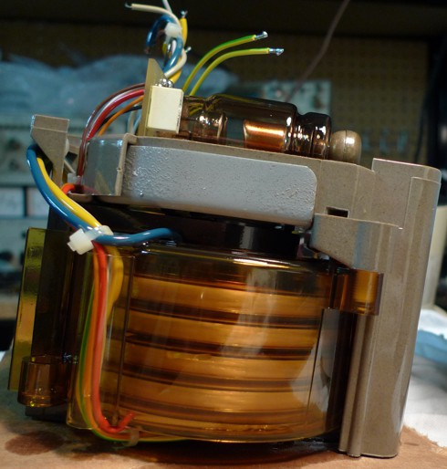
There are five windings visible, and these are the secondary windings. The top four are high voltage windings that will be connected in series. The winding on the bottom is a low-voltage secondary, and is probably used for monitoring the HV output voltage, although it might also be used to generate the xray tube's cathode current. More investigation is required.
The primary winding (the yellow and blue wires) is wound underneath the secondary windings. Winding the secondaries directly on top of the primary is a common configuration.
Ferrite Core
As can be seen in prior photos, the core of the transformer is an open cylinder. So it seems like this is an "air core" transformer, but on closer inspection, it is seen that the core cylinder is lined with a layer of ferrite. That liner "flows" to the bottom, then to one side, and becomes a solid tube of ferrite that goes up to the top of the transformer (the dark tube on the left of the transformer in the picture above), where it goes back to the center (becoming a tube liner again).
So the transformer is really like most transformers, in that it has a continuous core of a ferrous material. The core just happens to have a hole in it so the xray beam can flow unobstructed through the middle of the transformer (from top to bottom in the picture).
QUICK TANGENT ON "AIR GAPS"
This transformer is meant to be operated as a flyback transformer (a transformer operated in discontinuous mode), which means that energy is built up over time, and stored, in the magnetic field, and then periodically and quickly discharged into the secondary.
Ideal (and practical) magnetic materials store very little magnetic energy. In order to store and return energy to the circuit efficiently, a small gap is required.
This air gap increases the magnetic leakage (flux that does not couple the primary and secondary), and therefore also increases the inductance of the primary.
This transformer is no different. The gap is at the top of the cylinder lining portion of the ferrite core.
The Primary
The primary is wound with 20 AWG solid wire, with varnish insulation.
I measured the primary DC resistance at 0.13 ohms. With 20 AWG wire, this equates to a length of 150 inches of wire. The leads were each 9" long, so the core is wound with 132" of wire.
The core diameter is 2", so this means the primary has 21 turns.
Note: I have not dismantled the core, so I am assuming the primary windings are of the same wire type as the primary lead wires themselves. If the windings have more copper, it is possible there are more than 21 winds on it.
The Secondaries
There are four high voltage windings on the secondary. These are wound with many turns, using thin wire.
There is also another secondary, wound with thicker wire and fewer turns. For now, I will not focus on this winding, other than to say that one of the wires to this winding is labled "HV." The second wire for this winding is tied to the earth wire. This secondary winding is probably used to indirectly monitor the HV output of the transformer.
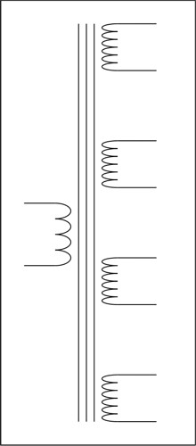
So here is a simple schematic of the primary and the four HV secondary windings:
In the next post, I will discuss how the high voltage DC output is created using the transformer and voltage doublers.
Discussions
Become a Hackaday.io Member
Create an account to leave a comment. Already have an account? Log In.