This post will examine the high voltage output circuitry.
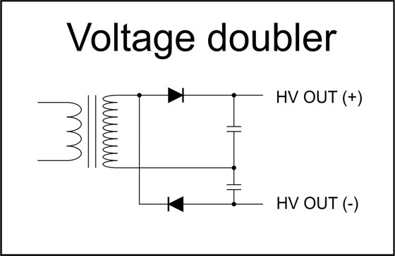
Voltage Doubler
The diode/capacitor circuit below is often used to double an AC voltage, while rectifying it to DC. (Note: Ignore the voltage increase from the transformer portion of the circuit. The voltage doubler is just the diode/capacitor portion of the circuit attached to the secondary.)
This type of voltage doubler is frequently called a Cockcroft–Walton generator or multiplier.
Imagine that this kind of voltage doubler were to be attached to each secondary winding in the xray transformer (see previous log entry) like this:
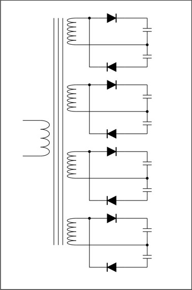
This would generate four DC outputs, with each one electrically isolated.
In the xray head the output of each voltage doubler is connected in series to create an output four times higher than each individual voltage. So the actual xray high-voltage circuit looks like this:
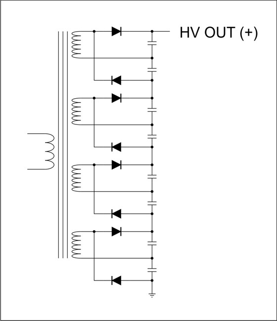
The high voltage output is typically 70 keV, and it connects directly to the anode of the xray tube.
The "ground" of the HV output is tied to the focusing ring of the xray tube, and is AC-coupled to the earth connection. (Full schematic to come...)
I really like this HV output topology. Frequently, HV circuits have a single large secondary winding to generate a very high voltage, and then a single array of diodes and capacitors to double (or quadruple, etc...) the output.
The arrangement reduces the high voltage stress by breaking it into lower-voltage, floating sections, and then stacks them to create the final HV output. Cool.
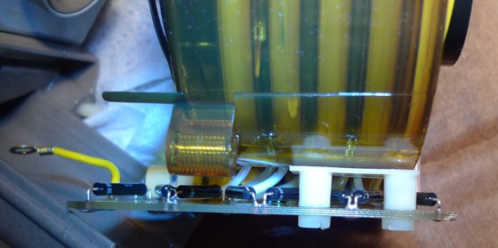
In the picture below, you see the top of the PCB that holds the voltage doubler circuitry. The HV + output is the yellow wire.
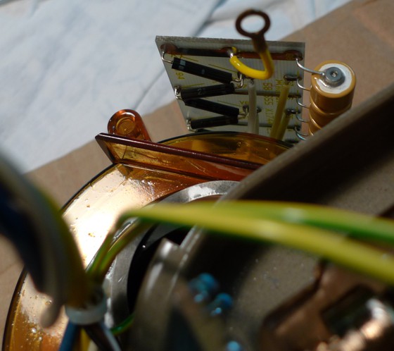
Below, you see the HV + on the left and the HV return (or HV -, or GND) on the right.
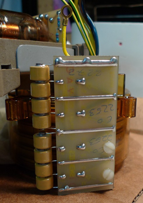
Below is a picture of the back side of the HV doublers PCB. The HV + output is on the top.
How to drive it?
What type of waveform would you apply to the primary to drive this circuit? What frequency, what voltage, what current?
I found someone who was selling this transformer online that said the transformer was meant to be driven by a 25 kHz square wave. This makes sense. The skin depth at 27 kHz is a large fraction of the diameter of 20 AWG wire, so going above 25 kHz reduces the current carrying capacity of the primary winding.
I experimented by driving the primary with a low-voltage sine wave, just to see what kind of output levels I would find. At frequencies around 20 to 25 kHz, with a drive voltage of around 200 mV, the output was around 20 to 30 VDC out. I found that the HV output voltage dropped off significantly above 60 kHz.
The 20 gauge wire of the primary should probably not be asked to carry more than around 10 to 15 amps.
At the full 70 kV output, at the full 8 mA or so, means the output of the circuit is 560 watts. So the input power to the circuit (power to the primary) is probably going to be at around 700 watts.(!)
So driving this circuit would probably require a half-bridge driver circuit, probably around 25 kHz, and probably using a supply voltage around 60 volts, maybe higher, at around 10 to 15 amps. Just a set of guesses.
Discussions
Become a Hackaday.io Member
Create an account to leave a comment. Already have an account? Log In.