 Bash Sarbora
Neptune is an Underwater Remotely Operated Vehicle (UROV) with some semi autonomous features. The main goal of the project is to create a hardware/software platform for a generic UROV system, so that anybody can build their own physical configuration around it.
My physical prototype is made of PVC and the thrusters are oriented in a vectored format, but nobody else would be limited to these configurations.
The general system overview looks roughly like this:
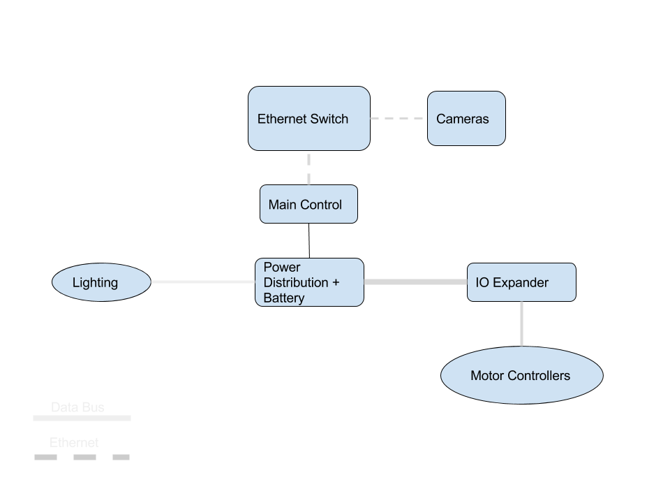
In my particular setup, the UROV is tethered via ethernet to a floating buoy on the surface with and Access point that the computer can connect to. This isn't required, I just found it easier to work with. The buoy will also have a GPS and data logging system connected to the network when I get around to it.
The PC application is currently written in python, but because all communication goes through TCP and UDP it can easily be written in almost any other language (maybe browser application in the future?)
In the actual UROV there is an IP camera, and the main controller connected to the ethernet switch. This setup has the benefit of a bunch of flexibility. I can add any number of extra IP cameras, or devices in the network.
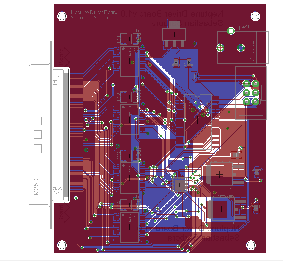
The control system is logically separated in a few different boards. This is mostly to allow them to be replaced and upgraded, as well as to give some flexibility with the physical configuration of the UROV.
The entire system is powered by two 11.7v Lipo batteries housed in the UROV.
Physical Configuration
I built the physical body of my UROV from various sizes of PVC, and a lot of caulk and marine glue. It is rectangular, with 3 central tubes that house the electronics. This physical configuration has been reimplemented and will be replaced soon.
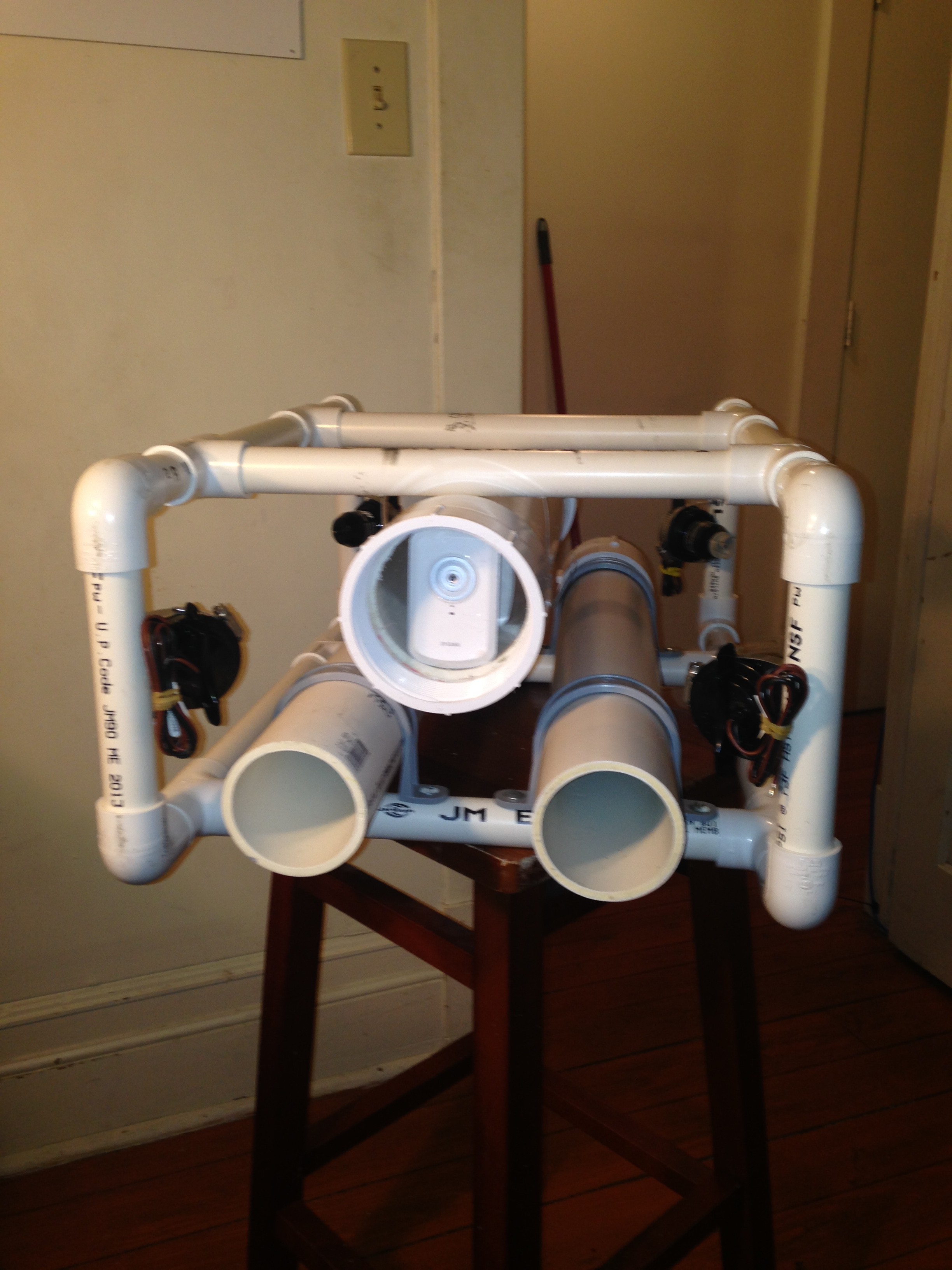
The center tube houses the 3 control boards, as well as the camera, and network switch. The two smaller tubes have super bright LED's on the front, and the left one houses the batteries.
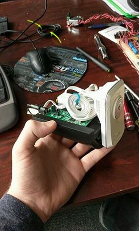
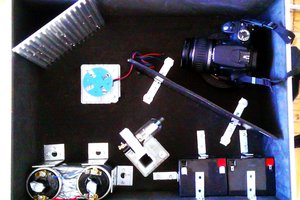
The electronics in the center tube are arranged in a "Core" all mounted to a piece of balsa wood.
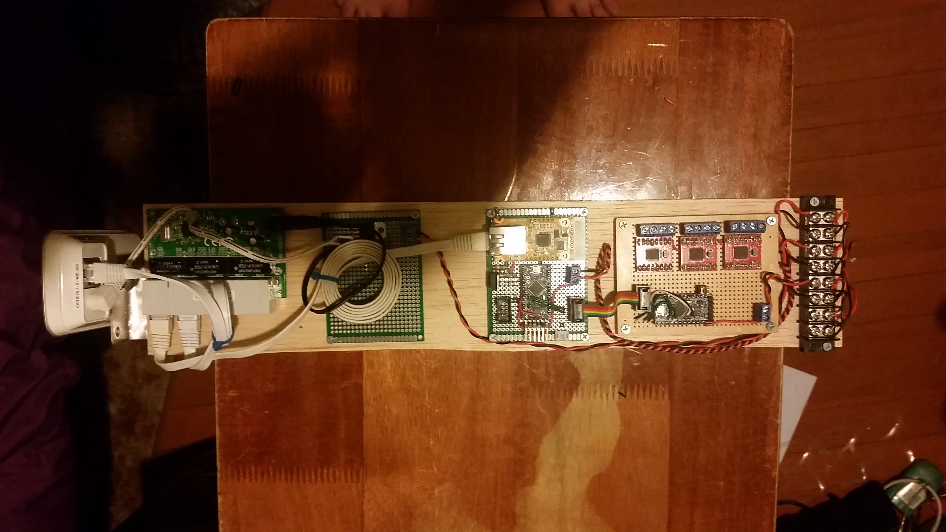
The parts, from left to right are the camera, ethernet switch, a power conversion board, the main control board, the motor controller/relay board, and a power distribution bus. The whole thing just slides into the back of the main tube and closed with a waterproof sealed screw cap. This is being replaced with new board designs and a 3D printed core.
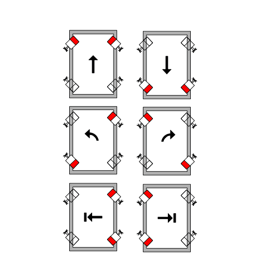
The thrusters are oriented in a vectored configuration. this configuration uses 7 motors to allow translation and rotation along every axis. This image shows how the thrusters are controlled to make those maneuvers.


 Paul Kocyla
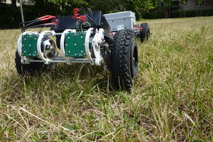
 Luke
Luke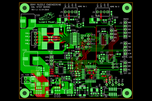
 Bharbour
 davedarko
Hi, I’m Alan, a Wiznet engineer. Thanks for your post. I'm very happy that you made a wonderful project using our products. You can get a lot of information by visiting our site. I hope you come and get a lot of information. If you have any questions, please feel free to tell me. Thanks again