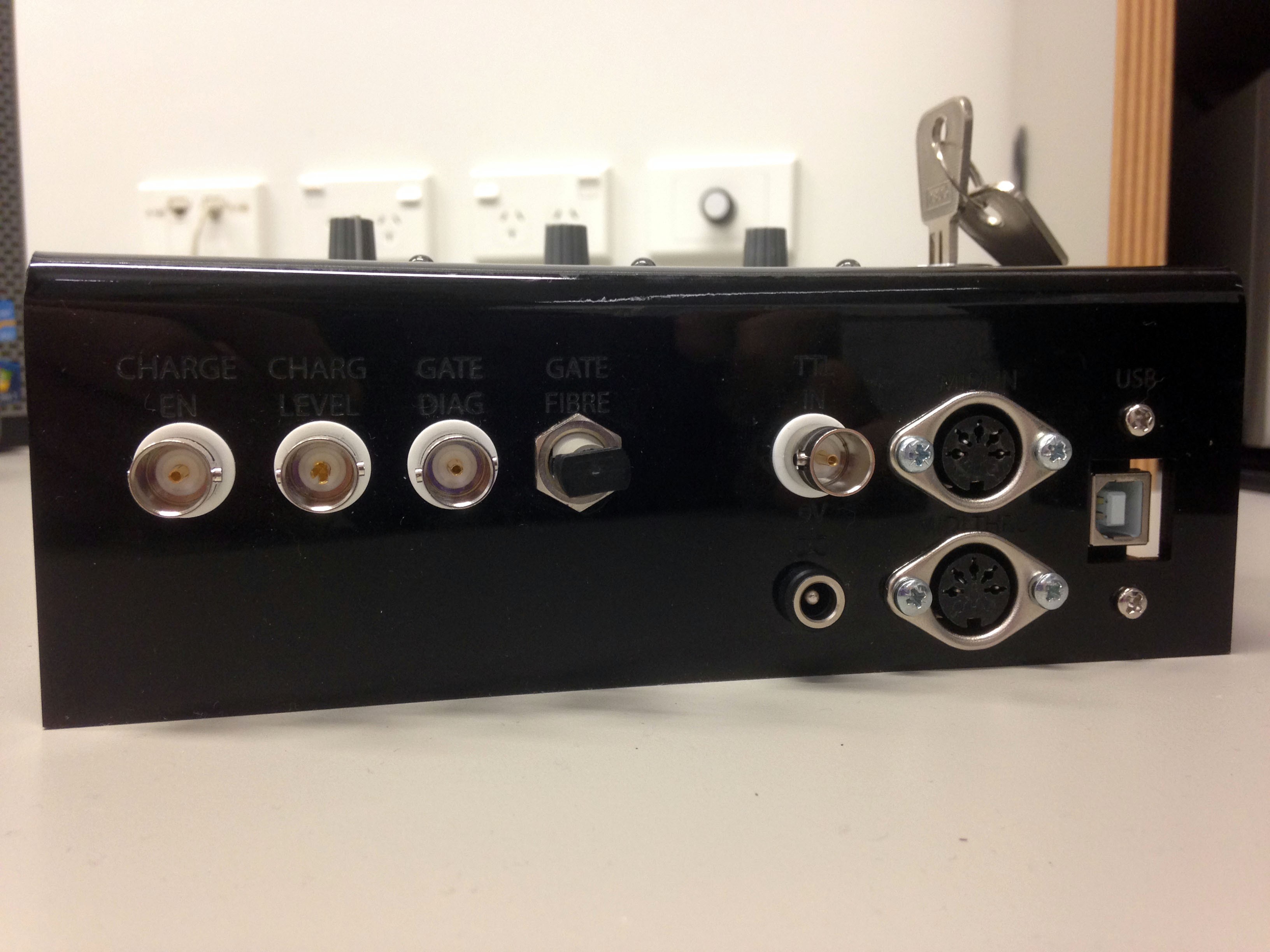
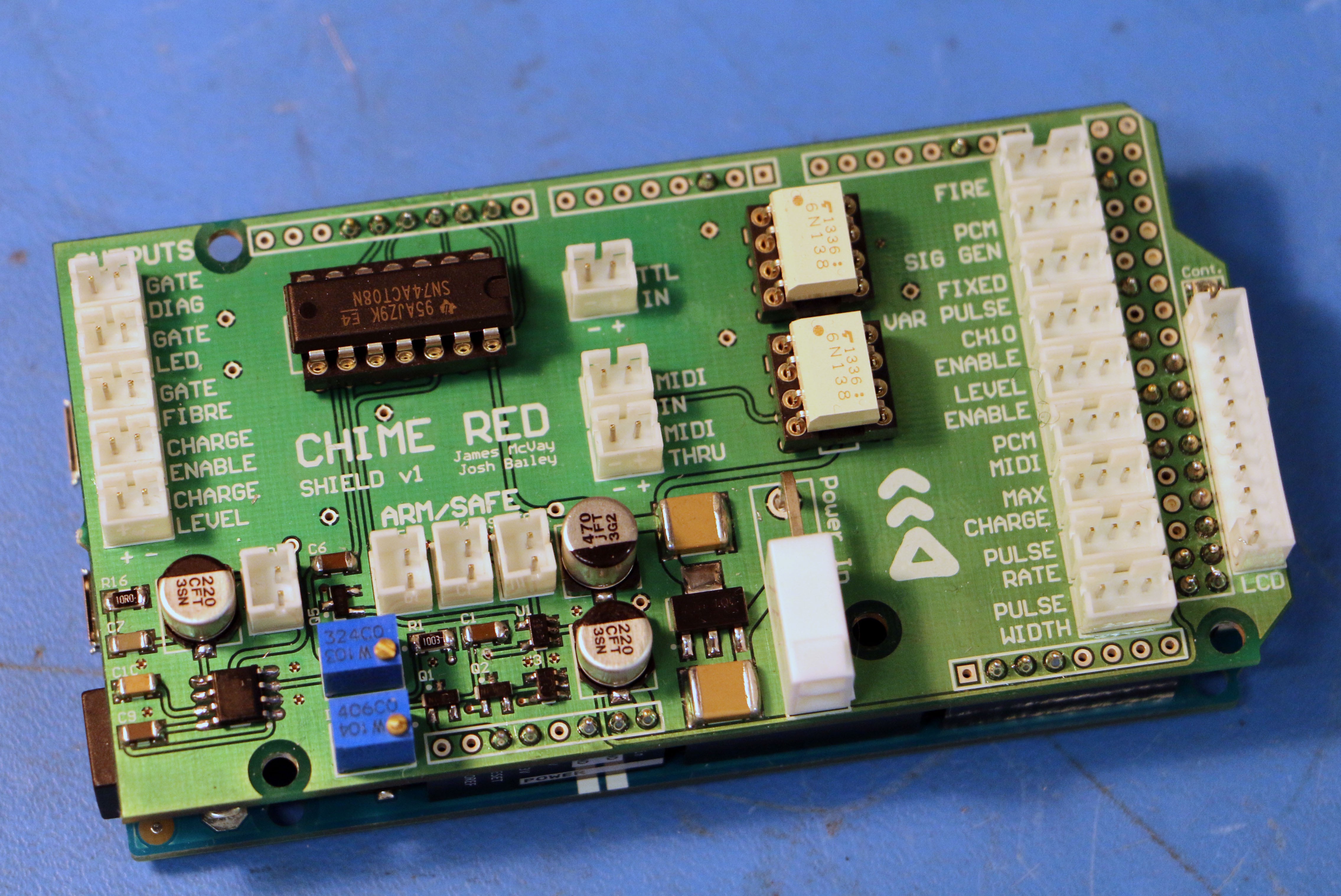
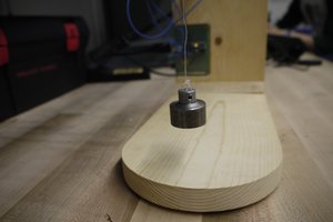
Hardware began with a custom Arduino Due shield with the various connectors and supporting components. Using this a test rig was created out of a piece of folded acrylic with the required buttons, Fibre output, MIDI I/O, speaker, and various BNC TTL Inputs and Outputs. Following this, features were CADed in SolidWorks to mill out a Hammond brand Die Cast box for the final product. Powder coated boxes were used, such that the labels for various functions could be etched with a laser engraver. Four boxes were built, with around 100 wires, soldered on one end and JST crimped on the shield end! I highly underestimated the amount of time this project would require, but it was well worth the result.
See the project log for the various stages of the design with photos, be sure to click "View all 5 project logs"!

 Evan
Evan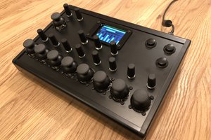
 Liam Lacey
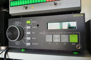
 smartroad
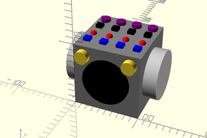
 jason.gullickson
Schematics and Arduino code available somewhere ? I watched Josh's talk at CCCamp2015 and want to build one for my DRSSTC...