 icstation
Hello friends, the engineers of ICStation team have made the amazing remote control clock with the DIY kits.Now we will show you the making steps in details for your reference, especially the important welding procedure for your reference.
Five functions of remote control clock:
1. On time alarm (7-22 o'clock chime, hourly chime can also be turned off.)
2. Five channel alarm clock (can be turned on or off, respectively, with the shortcut keys to quickly turn on and off the main switch 5-way alarm.)
3. Error Correction (with software correction X days Y seconds, manually open the correction function, set the X and Y parameters can, Y is positive for X days plus Y seconds, Y is negative for X days minus Y.)
4. Memory when power off (dedicated clock chip + back-up battery, even if the external 5V power outage, battery-backed clock chip in the case can continue to travel time, eliminating the need for re-calibration after power off when the trouble.)
5. accurate time (clock chip oscillator selected error 5PPM, travel time from the hardware to ensure precision; with error correction procedures, can in 30 seconds April error control range)
General description of DIY kits
Kit model: BCL-1
Package name: 4 -bit remote control clock
PCB size :Φ57mm 1.0mm thick
Working voltage:5V(Powered by USB)
Lamp body size: Φ60mm
Step 1: Schematic circuit diagram

Principle Description
The whole system is made up of MCU minimum system,infrared receiver circuit,display circuit,buzzer circuit,the clock chip and power supply.
1.MCU minimum system:U1(STC11F04E),POR made up by C1、R5,clock circuit made up by C2、C3、Y1
2.Infrared receiver circuit:U3 is responsible to receive the signal that is sent by remote control.After amplification, the whole line is output from 1 pin and send to MCU to process.
3.Display circuit:U4(74HC138D)3-8 decoder、Q1-Q4、R7-R14 and digital tube which has the same anode.
4.Buzzer circuit: R6、Q5 and LS1,key tone of the clock, the sound of hourly chime, the bell of clock. Those sound is output from P3.1 port of MCU and make a sound by Q5 driving LS1
5.Clock chip:U2(DS1302)、Y2、C5、C6 and BT1
6.Power Supply: J1 connect power line and C4 smoothing.
Step 2: Weld SMD IC and resistor

You should pay attention to the direction of IC.
Step 3: Weld DIP component on other side
 You can change the pin shape of IR sensor in order to install beautifully.
Step 4: Weld MCU and clock IC

This step should pay attention to direction
Step 5: Weld battery box and buzzer

Weld battery box and buzzer in right direction. Their pins should cut short as soon as possible on other side.
Step 6: Install LED Segment Displays

You should install LED Segment Displays in right direction.From now on, we have installed clock controller board.
Step 7: Deal with lamp body

Now, we began to deal with lamp body.
Step 8: Take down trigger spot for lamp body by blade

You can heat trigger spot by soldering iron if it is hard to take down trigger spot. The USB power apply cable will though it.
Step 9: Deal with the interface of lamp body

The bulge that can be used to fixed lampshade should cut some thickness on a cycle by blade or scissor. ( Please take care of your fingers!!!)
Step 10: Install USB cable and take a knot

You should install USB cable and take a knot in the right place.
Step 11: Red cable is VCC and black or blue cable is GND.

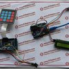
Step 12: The effect after connecting to the power

OK, we have installed lamp. We can see the effect after connect to power.
Step 13: Install remote control

Weld SMD component.
Step 14: Install shrapnel

It can be cut if the pin is long.
Step 15: Install the other shrapnel

Step 16: Install IR LED

You should pay attention to direction. You can see the long pin and short pin in picture.
Step 17: Install shell

Step 18: Demonstration effect


 oneohm
 Henry York
 fletcherpaul79
 danjovic
One of the more interesting projects I've seen so far from ICStation. However:
"Install the shrapnel", "Install the other shrapnel"
You should check your translator. :) Those are battery contacts. Shrapnel is sharp broken pieces resulting from an explosion.