 fl@C@
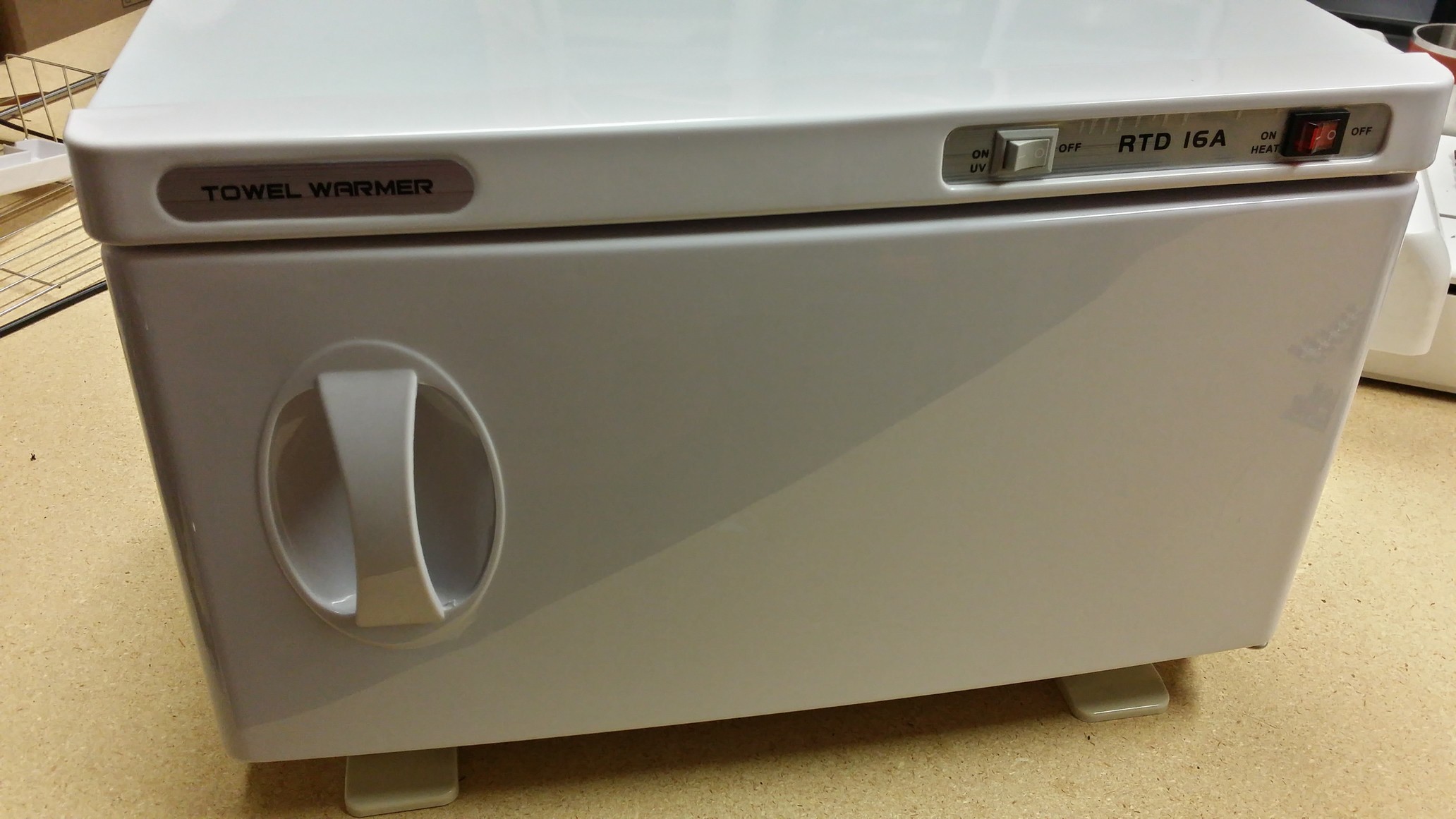
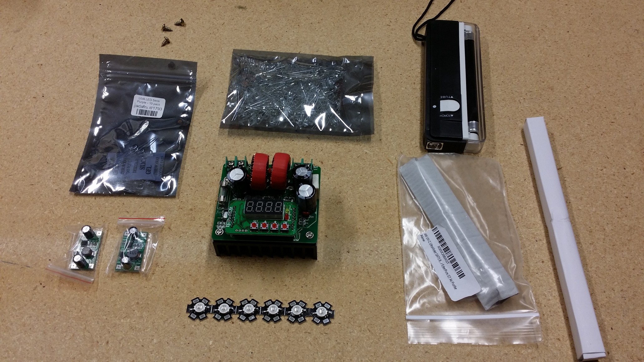
fl@C@A conversion of a readily available "towel warmer and sanitizer" into a UV exposure 'oven' for exposing photosensitive film or photosensitized PCBs for etching, and for exposing UV Ink solder mask and silkscreen layers..
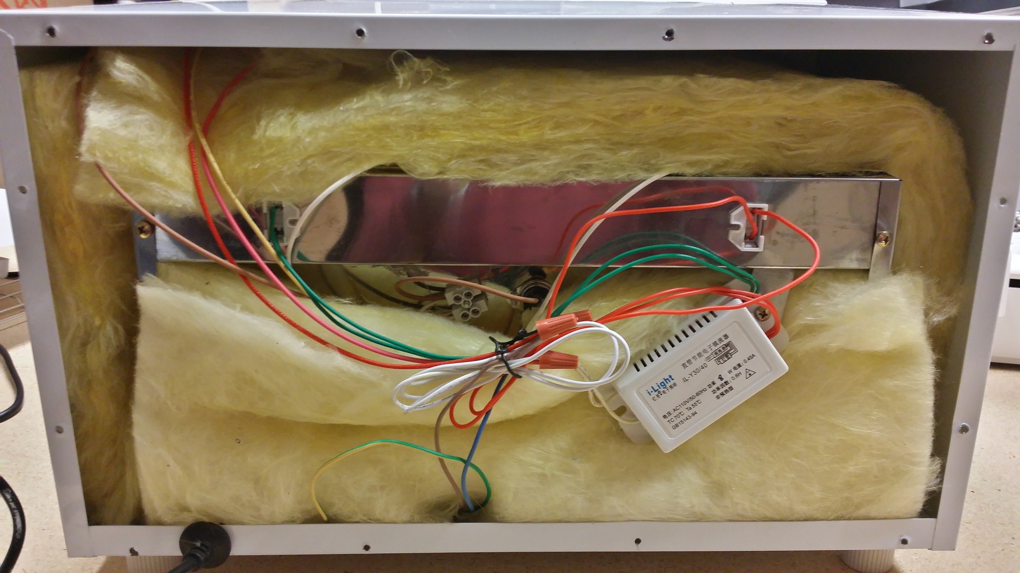
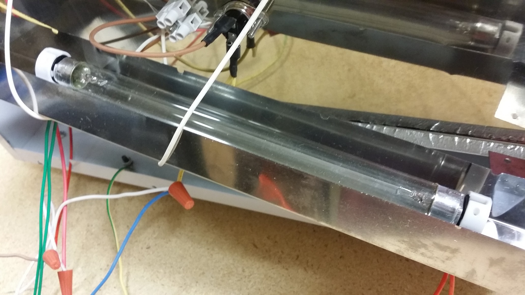
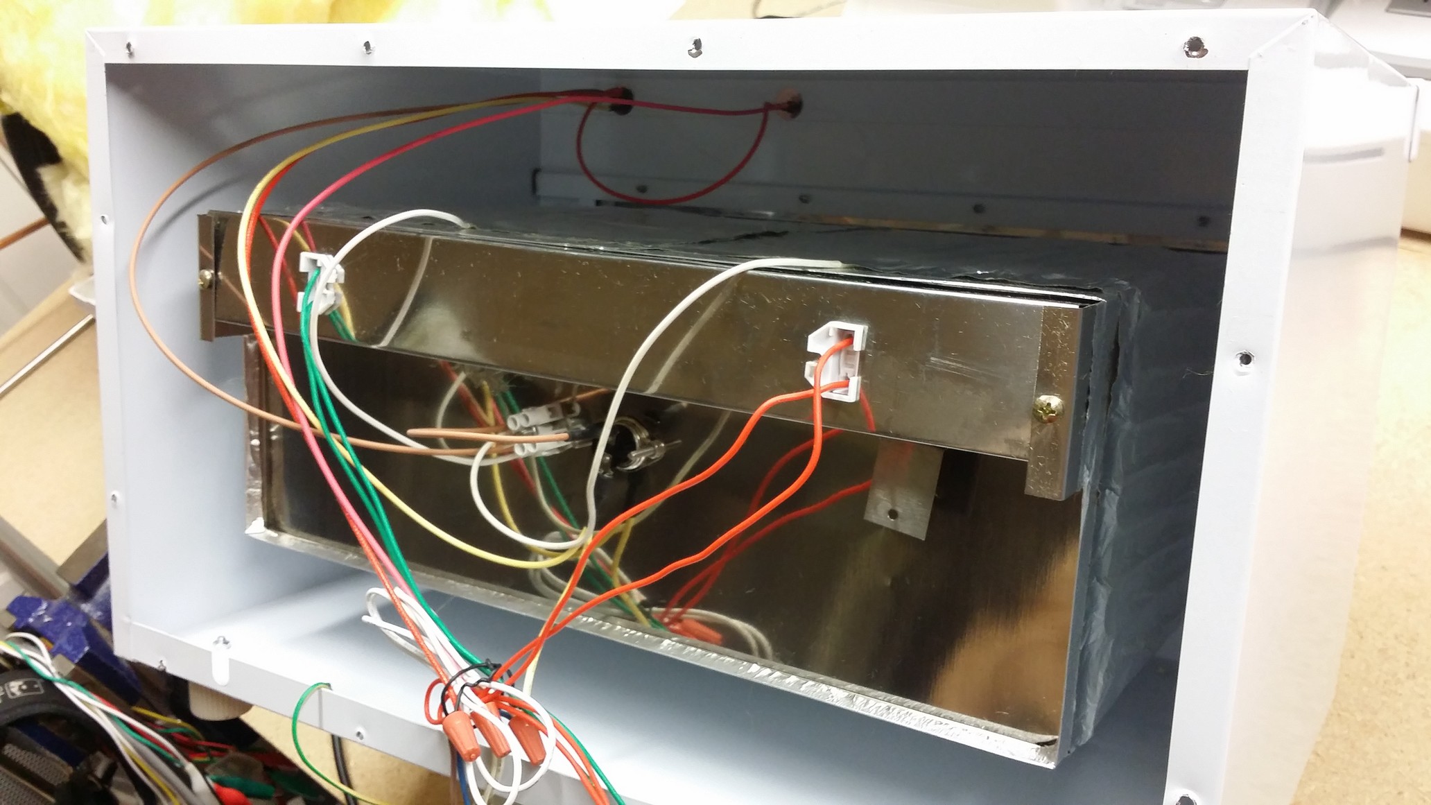
Mostly accomplished by removing most of the guts from the 'oven' and replacing it with microcontroller controlled UV LEDs, etc..
I will also create a project here on how to use the exposure oven once you've converted it...
This is also a result of the ramanPi and my needs for making better PCBs.. keep and eye out on the project for more fun!
This project uses the templates created from the Tonerless PCB Templates for UV Exposure project...

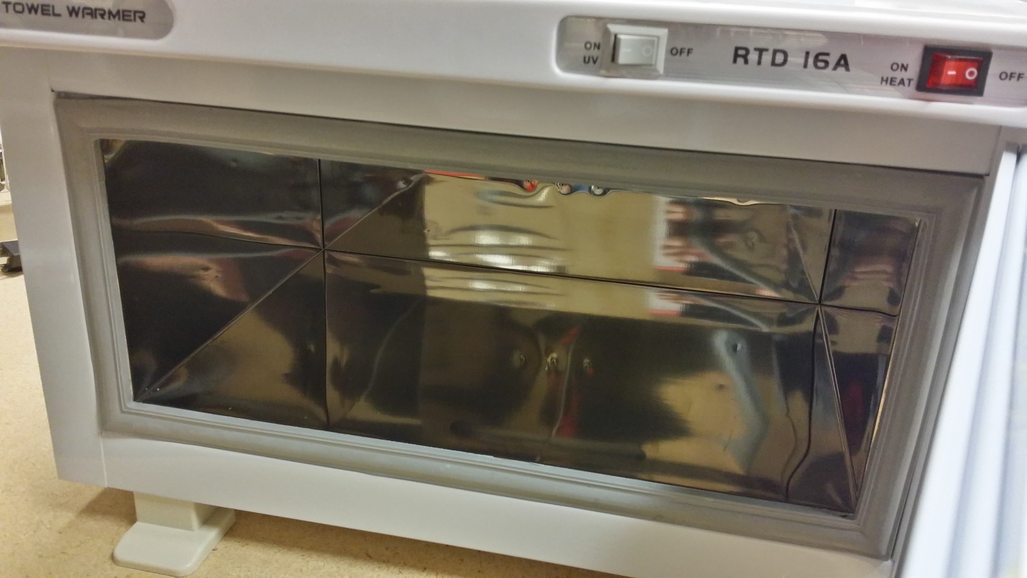
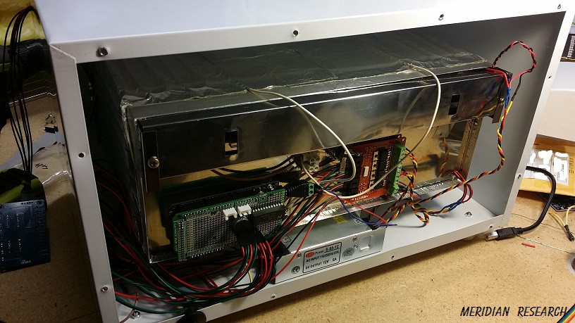
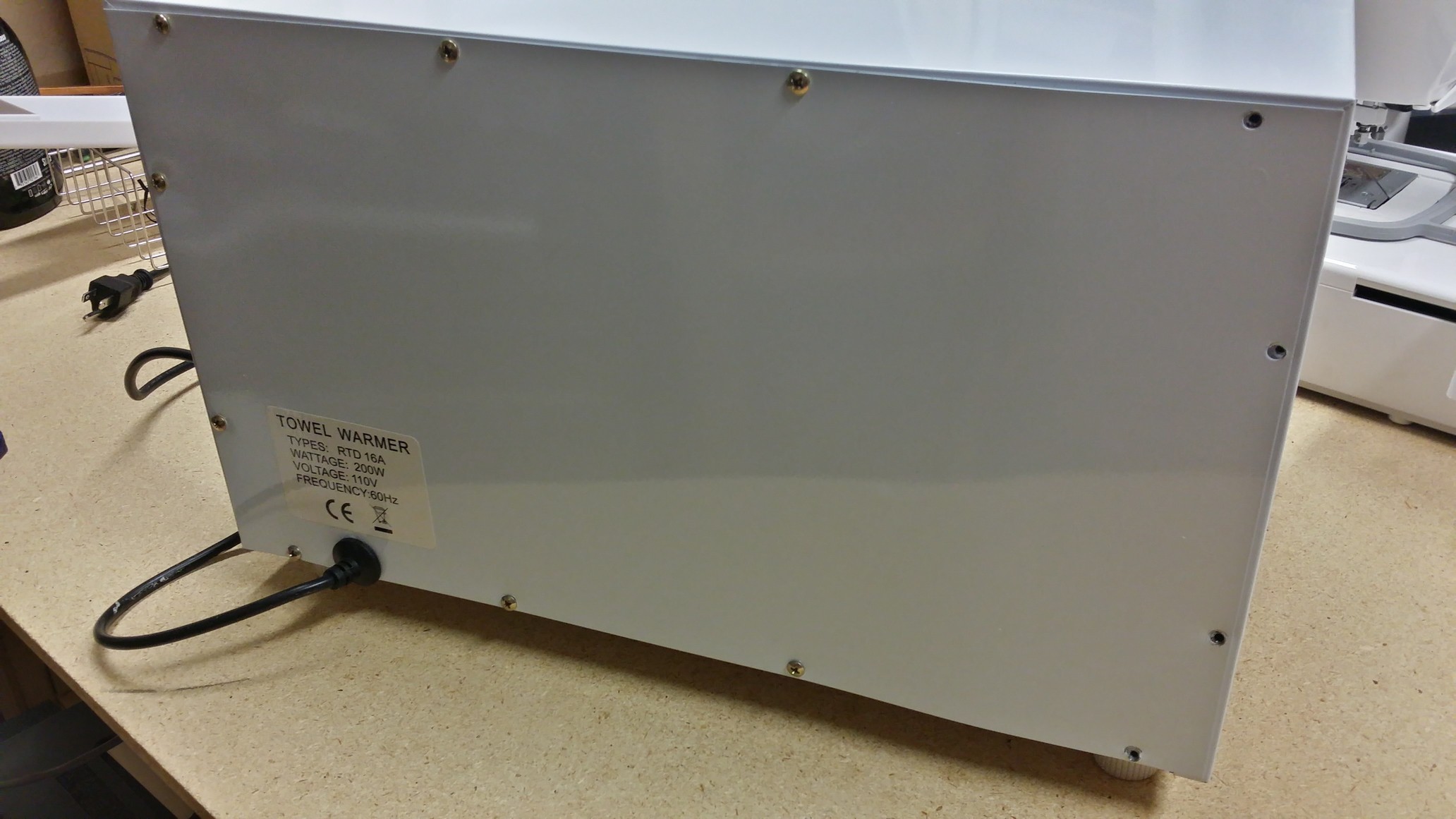
The "Oven" is just a 'towel warmer' from eBay..

The inside is nice shiny stainless steel, which makes for a nice reflective surface...
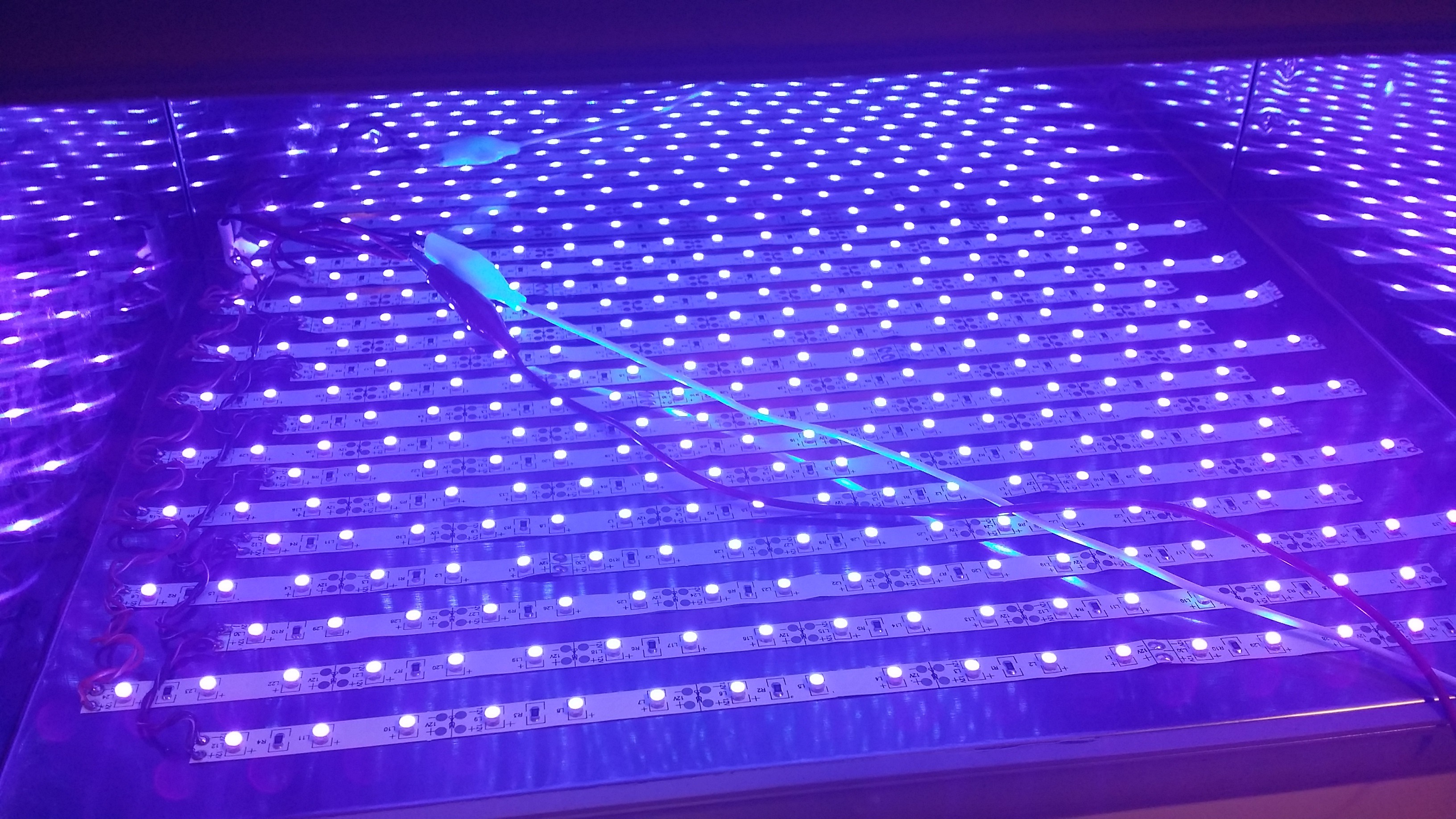
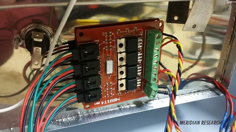
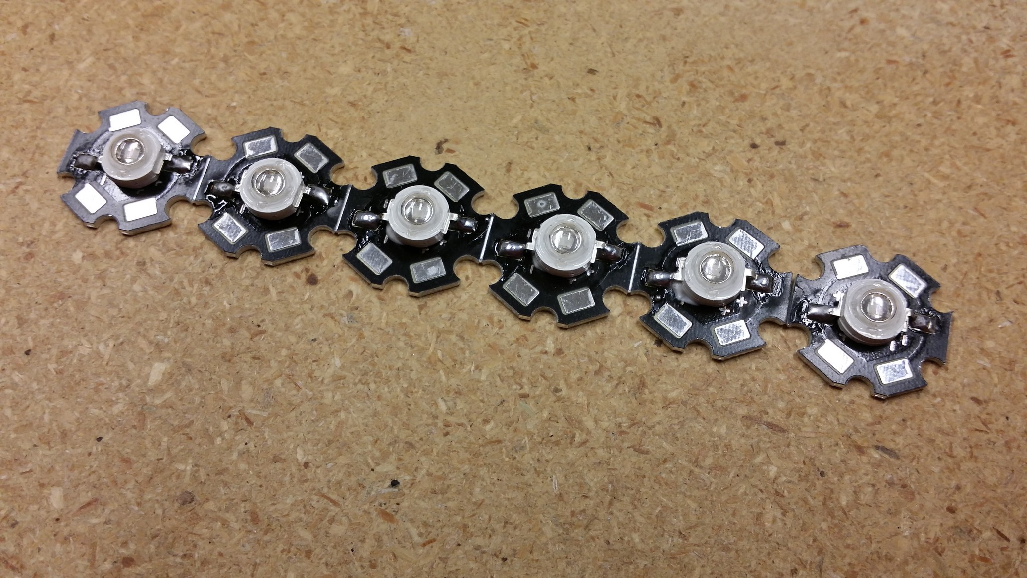
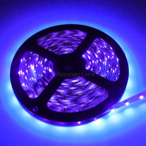
About 300 LEDs are mounted to the inside surface on the bottom and top...
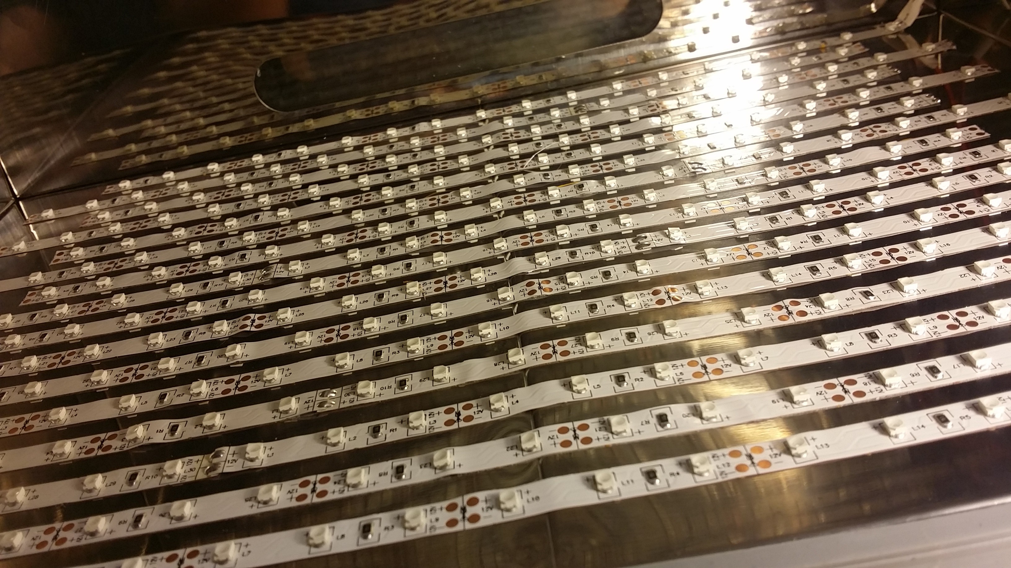
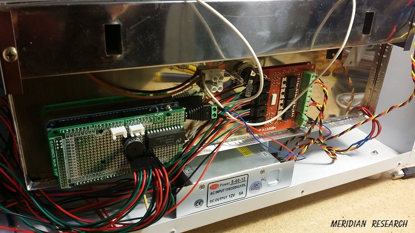
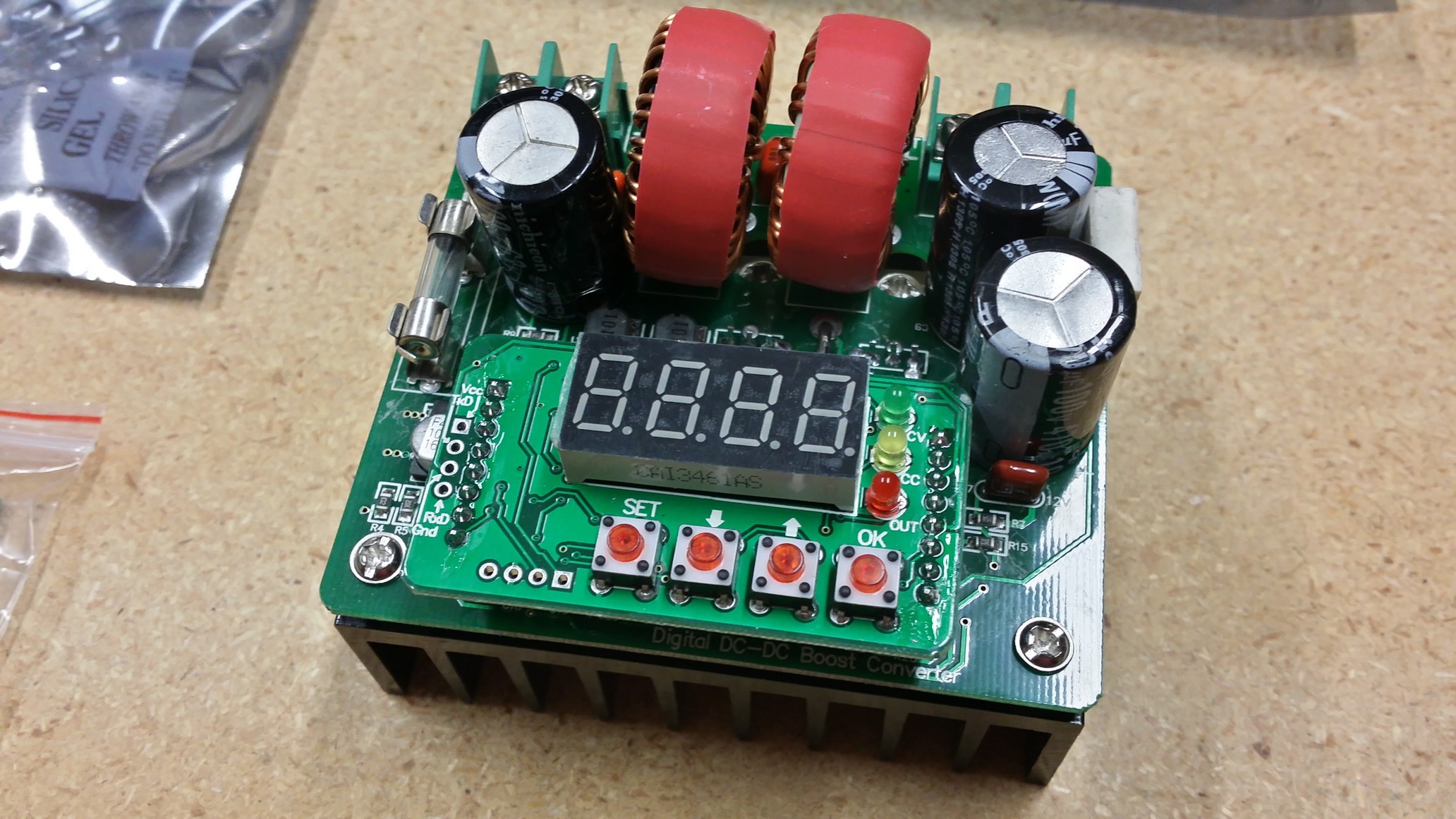
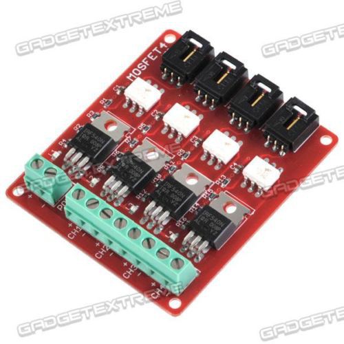
And a microcontroller controls the lighting which is split into four banks... top and bottom have two interleaved banks controlled by mosfets.. PWM can be used to control the brightness as well..

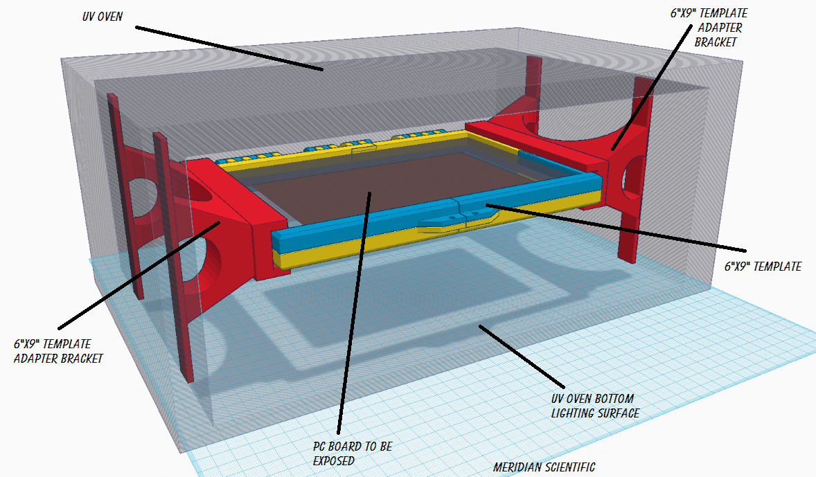
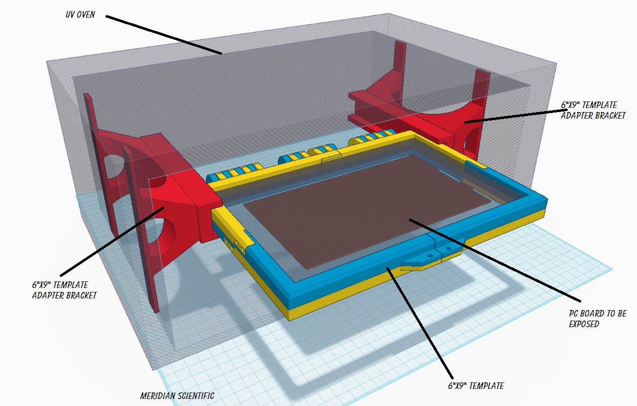
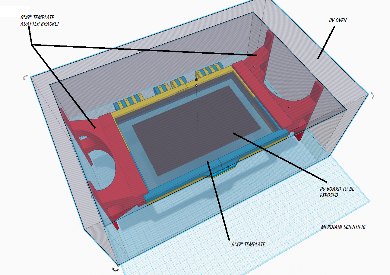
This is still in progress.. The ultimate design will have a small rack where a sandwich of two 1/4" borosilicate glass plates with a circuit pattern etched in aluminum will provide the stencil... This is described in my other project http://hackaday.io/project/4565-glass-pcb-templates-for-tonerless-pcb-production where I will describe how to make those.. What you're left with will be a reasonable solution to making the same boards indefinately with a stencil that doesn't break down in uv, the borosilicate is used because of the excellent tramission in the uv range...


 HybridAir
 HP (@banjohat)
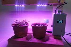
 RossGK Tangibles
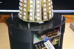
 SUF
SUF
Interesting. So far, a box from a dead scanner, filled with UV LEDs, is the most common setup seen for a UV PCB exposer. The advantage is that the mask film can be pressed between the photosensitive PCB and the glass sheet of the scanner.
With the oven design, how do you plan to make the film mask to stick to both sides of the PCB?