First, here is what i have:
A Element 14 Beaglebone Black Rev C with 4 Gb eMMC runing debian
A 8 inch 4:3 ratio LED backlight LCD panel with 800x600 pixels
Prototype prefboard, wire mm.
What else do i need?
1. FPC cable connector, 50 pins from ebay (ebay link)
2. 50 wires cable and connector, will only need them for prototyping.
3. Div. stuff for soldering the cape.
4. Datasheet for the LCD panel. I found this one on the internet, not exacly the same number as my panel but it seems like they are compatible (AT080TN52 Final- SPEC(V01)). I needed to trace the signals from the original driver board to verify that all the signals are on the same pins of the LCD connector.
Now that i have all i need, the next step is to lean how to make capes for the bbb. There is alots of information about how to load a device tree, how to make the bbb load/unload a specific cape at start etc. and as a newbie, I'm really grateful that there is so many good documentation in this topic. There is no better place to look if you want to make your own LCD cape than Circuitco's 7 inch cape BB-BONE-LCD7-01. The only downside is that this cape is 800x480 and that the pixel clock is runing at 30 MHz while my panel is a 800x600 and 40 MHz.[Edit: seems like that other timing specs like front porch, back porch mm is way off too.]
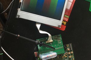
For the first test, I wired all 16 data signal and 4 control signal to my LCD the same way as the CircuitCo LCD7. Then i used all the LCD bias voltages ( VACC, VGH, VGL, VCOM) from the old driver board and set the scaning direction to Lefl to Right, Up to Down, no Dithering and Data Enable mode.
I load the original device tree for CircuitCo BB-BONE-LCD7-01:00A3 as it is just to test and ......Tada.. I have a picture on my LCD ;)
Wow that's good news isnt it. This mean that the hardware is working perfectly. The display driver is for a 800x480 pixels display, so the weird picture that I get is expected, what i didnt expect to works is the pixel clock that is 30 MHz instead of the stated (typical) of 40 MHz for my panel....
Now that I know this can work. The next steps is to modifiy the device tree to fit my panel and recompile it. Don't think there will be any disaster there anyway, but i will keep my fingers cross.
Update 2015-01-08:
Now I have my native resolution on my display :) And all I can say is that it was easy to get the hardware to work but the software/driver bit is quite confusing and time consuming.
I end up using "kms_force_mode=video=LVDS-1:800x600M@60e" in the uEnv.txt file. That M before @ is the key here! and you can find your video adapter from "/sys/class/drm/card-0-LVDS-1"


 Wenting Zhang
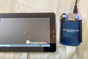
 Kumar, Abhishek
 Abraham Limpo
Hi, I don't know if miss some point, but where is your schematics for this project? can you share it?.
Best Regards D.B.Paiva