icstation
At the beginning of the new year, robot/Smart Car hobbyists and students (like all of you) about engineering, science and technology are busy with preparing for the robot competitions now.
It's the great time to show the world your imagination and potential now.
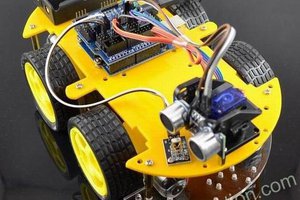
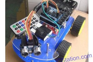
ICStation R&D department has just finished this obstacle avoidance intelligent smart car which based on the STC89C52 MCU. It features with the function of obstacle avoidance, infrared remote control and Bluetooth remote control system. It improves a lot on the usage of this intelligent smart car via the connects of various modules and controller.
BTW, this is just a sample which based on 51 MCU for your reference. You also can use other MCU to build your own gear. If you like 51, just leave us your email address to get the testing code.
Outline
- Main Parts Parameters
- Components
- Steps for installation Intelligent Smart Car
- Main Components Introduction
Parameters for your reference:
1. Motor parameter
- Power apply:6V-9V
- Reduction gear ratio:1:48
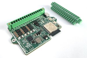
2. Dual L298 Driver Motor Module
- Driver chip: L298N dual H-bridge driver chip
- Drive section terminal supply area VMS: +5V ~ +16V. (The supply area should be +6V~+16V if the electricity should be taken in the plate.)
- Drive section peak current Io: 2A / Bridge
- Logical part of the terminal supply area Vss :+5V~+7V (the electricity can be taken in the plate +5V.)
- Logical part of the operating current range: 0 ~ 36mA
- Control signal input voltage range (IN1 IN2 IN3 IN4):
Low Level:-0.3V≤Vin≤1.5V
High level: 2.3V≤Vin≤Vss
- ENA ENB
Low Level:-0.3≤Vin≤1.5V (Control Invalid Signal)
High level: 2.3V≤Vin≤Vss (Control Valid Signal)
3. Ultrasonic module
Working Voltage : 2.4~5.5v
Static current: Less than 2mA
Detection distance range: 0~4.5m
Components
1 x 4WD Smart Car Chassis $31.54
4 x Motor Reduction
1 x 7.2V Battery pack
1 x Speed Sensor $5.6
1 x L298N 4 Channels Step Motor Driver Module
40 x Dupont 20cm Color Cable
1 x SG90 Micro Servo Motor $3.04
1 x Bluetooth Transeiver RF Module
1 x US-100 Ultrasonic Sensor Module $5.46
1 x 4 Channel Tracing Module
1 x 51 MCU
4 x Infrared Sensor Obstacle Avoidance Module Probe
1 x Ultrasonic bracket
1 x Infrared Remote Control Module $2.8
1 x Steering Gear Bracket
6 x Copper Cylinder M3*45+6
1 x M3*7.5 screw
Step 1: Installation of smart car wheels


- Fix the motor and the base plate with 2pcs fixed plates and 2pcs screws (The side with the line ends of the motor should be faced inward.)
- Install the encoder and wheel
(no need to do this if you have the 4WD kits on hand)
Step 2: Install the Speed measuring module on the baseboard

Speed Senor Module is for measuring the speed of intelligent smart car.
- It uses the correlation photoelectric slot type which can be triggered, as long as the transparent objects go through the groove. Output 5v TTL level.
- Use the schmitt trigger pulse jitter which is very stable and can be used for the smart car speed measurement, distance measurement and so on!
- Four pin definition: +5 GND OUT1 OUT2
OUT1, OUT2 are output level which can be connected to the microcontroller IO port directly. And each circuit will be with a LED indicating its output state.
Step 3: Install the 4pcs of obstacle avoidance probes on the baseboard

Step 4: Fix six pillar with 3.5cm on either side of the baseboard

Step 5: Fix the 51MCU module, 4 channel tracing module, Dual L298 drive module on the top plate

1) 51 MCU
51 MCU is based on STC89C52 MCU. Our testing code is on the platform of STC89C52.
You also can use other MCU to build your own gear. If you like 51, just leave us your email address to get the testing code.
2) 4 Channel Tracing Module
It provides smart car, robot and other auto machines with solutions on the Multipurpose infrared detection system.
The probes are consisted of the discrete components, such as the infrared transmitting and receiving tube. And it uses the LM339 voltage comparator.
Parameters...
 Electroniclovers123