lukasz.iwaszkiewicz
First and foremost, please forgive me for inconsistencies that are likely to occur in following description, as it is written post factum, and the whole project was meant to teach me something about analog electronics and bipoar junction transistors in particular. After all I'm a electronics enthusiast and amateur, not an expert. On the schematics you'll find half of the circuit actually built. Due to lack of appropriate elements in LTSpiceIV (it's an excellent app even though it runs only on windows / wine, and its wine compatibility is flawless) I used V1 instead of photo-diode (I'm not sure if it is a good choice, but I decreased its voltage dramatically to simulate voltage drop due to the high output impedance of the diode circuit).
Speaking of which, I didn't know what is the exact output impedance of the diode circuit (depicted on the left), so I put Q4 as a emitter follower stage which lowers this impedance. The signal previously revolving around 0.25V and spanning from 0V - 0.5V range, now is at 0.9V DC due to one diode voltage drop (0.65V in this case).
Next stage i.e. Q1 is of a common emitter configuration and its sole purpose is to invert the signal (which don't get amplified).
Q2 further decreases the output impedance, and voltage gain is still an unity.
And finally the last stage inverts and amplifies the signal a little bit. Now the signal spans from 2.8V (when diode is over white region of a track), and 1V when the diode travels over a black region.
R4 is the load and symbolises the motor. Whole robot is powered from a single li-po battery (3.7V) from old mobile phone. Charging circuitry is to be done.
Lessons learned :
- I find amplifying DC signals with BJTs difficult. For me it is difficult to bias them, they easily saturate etc. Most of examples I found were capacitive coupled which is suitable for AC signals. Operational amplifiers are way better in my opinion for this purpose.
- Using a photo-diode is tricky.
- The operation of motors should be rather on-off than this. I think I misunderstood the principle of line followers and made the circuit "to linear". Nonetheless it still works.
- TODO : impedance calculations : resistor values aren't from nowhere, I've got calculation somewhere, but dunno where.
- TODO : Photo-diode circuit. It consists of photo-diode and resistor in series if I remember correctly.
PS :
- Don't hesitate to criticise it, but remember that this is my first serious analog circuit :D
 Zach Armstrong
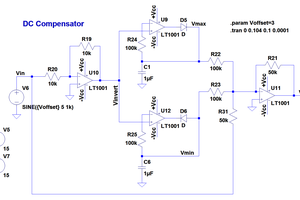
 Adam Gulyas