 Jarrett
Plunking away at this, a few minutes here, a few minutes there.
The project is broken up into three schematics.
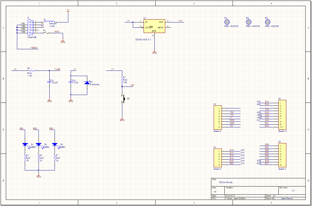
Main schematic. Nothing new here, really. Still need to add some more USB protection.
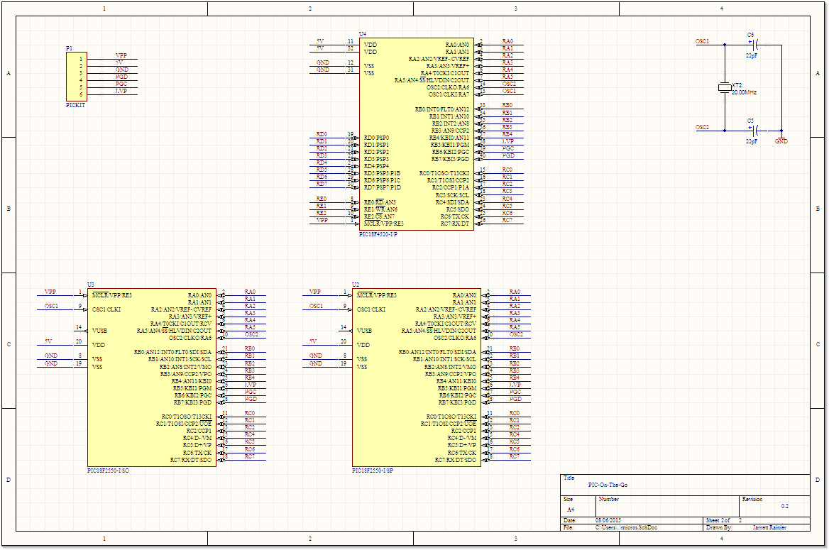
Main micros. I've got three footprints here, but it's all a lie. The top one is a big 40-pin wide package DIP IC, the bottom two are skinny 28 pin packages. One is DIP, one is SMD. Overlapping all of those footprints, along with Microchip's strategy of locating key function pins(like power) in the same location along all of their lines means that these boards will be able to hold and program a huge amount of different PICs in the 8-bit family.
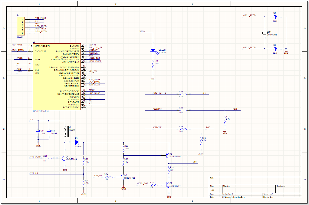
Beginning of the PicKit-On-Board. Microchip seems to like using a specialised circuitry and low-voltage programming when they do this for their dev boards, but that's a crutch. Not all PICs support LVP, and they need to have it configured in software. This board will work on all PICs that the PicKit 2 works on (which is most of them), and if the users wants to pop off their programmed chip and use it standalone, this saves an extra IO pin for whatever they like.
The embedded boost controller is super cool, too. If the user has their own programmer (or two of these dev boards) and is super clever, they can program the programmer chip and play around with the power supply generator.
The last schematic needs a whole bunch of cleanup. Component names are duplicated, etc.
Discussions
Become a Hackaday.io Member
Create an account to leave a comment. Already have an account? Log In.