 Anthony
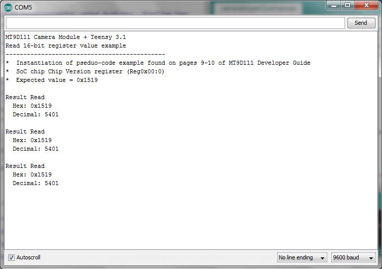
// Anthony Balducci - 05/15/2015
// MT9D111 16-Bit Register Read Example Arduino/Teensy 3.1 code

#include <i2c_t3.h> // Brian (nox771)'s I2C Library for Teensy, works much better than standard wire library.
                    // Configure the Teensy for 72 MHz (no overclocking) for most reliable results

void setup() {

 analogWriteFrequency(20, 8000000); // Teensy 3.x specific code -- Specifies a 8 MHz clock out signal for XCLK on MT9D111 on pin 20
 analogWrite(20, 128); // Starts PWM output with ~50% duty-cycle

 Wire.begin(I2C_MASTER, 0x00, I2C_PINS_18_19, I2C_PULLUP_EXT, I2C_RATE_400); // Configures I2C to run as master, pins 18 (SDA) / 19 (SCL), external pull-up resistors and 400 KHz I2C Rate
 Serial.begin(9600); // Open serial port at 9600 baud
 delay(5000); // Optional delay -- Provides user five seconds to open serial monitor

 Serial.println("MT9D111 Camera Module + Teensy 3.1");
 Serial.println("Read 16-bit register value example");
 Serial.println("---------------------------------------------");
 Serial.println("*  Instantiation of pseduo-code example found on pages 9-10 of MT9D111 Developer Guide");
 Serial.println("*  SoC chip Chip Version register (Reg0x00:0)");
 Serial.println("*  Expected value = 0x1519");
 Serial.println();
}

void loop() {
  delay(5000); // Optional delay between read tests

/* The MTD9111 Developer Guide states that 0xBA and 0xBB are the default read/write addresses respectively.
   However, it is important to note, while converting 0xBA and 0xBA to binary at first 'appears' to give us
   two distinct addresses:

   (Write) 0xBA --> 10111010
   (Read)  0xBB --> 10111011

   The two values only different in their LSB (least significant bit), or in this case, the first value on the
   'right'. The '0' / '1' in this position is what specifies the write (0) or read (1) condition accordingly.
   In the Arduino language the LSB read/write portion is already built into the Wire.write / Wire.read commands,
   thus the original register addresses specified must be truncated by the read/write bit to seven bits, leaving
   us with 1011101 --> Ox5D in both cases.


*/
  Wire.beginTransmission(byte(0x5D)); // Begin I2C transmission at MT9D111 default I2C device address
  Wire.write(byte(0x00)); // Specify register to be read
  Wire.finish(); // Wait to ensure transmission is complete
  Wire.endTransmission(I2C_STOP); // End transmission, including required 'stop' command

  Wire.requestFrom(byte(0x5D), 2, I2C_STOP); // Listen back for two bytes of data, with required 'stop' command once transmission complete
  int16_t result = ((Wire.read() << 8) | Wire.read()); // Bit-shift the first byte, concatenate and store

  // Output results
  Serial.println("Result Read");
  Serial.print("  Hex: ");
  Serial.print("0x");
  Serial.println(result, HEX);
  Serial.print("  Decimal: ");
  Serial.println(result);
  Serial.println();

} // Loop till canceled
Discussions
Become a Hackaday.io Member
Create an account to leave a comment. Already have an account? Log In.