 Orlando Hoilett
1. Continuous heart rate monitor
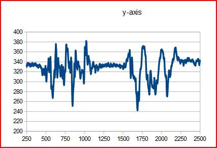
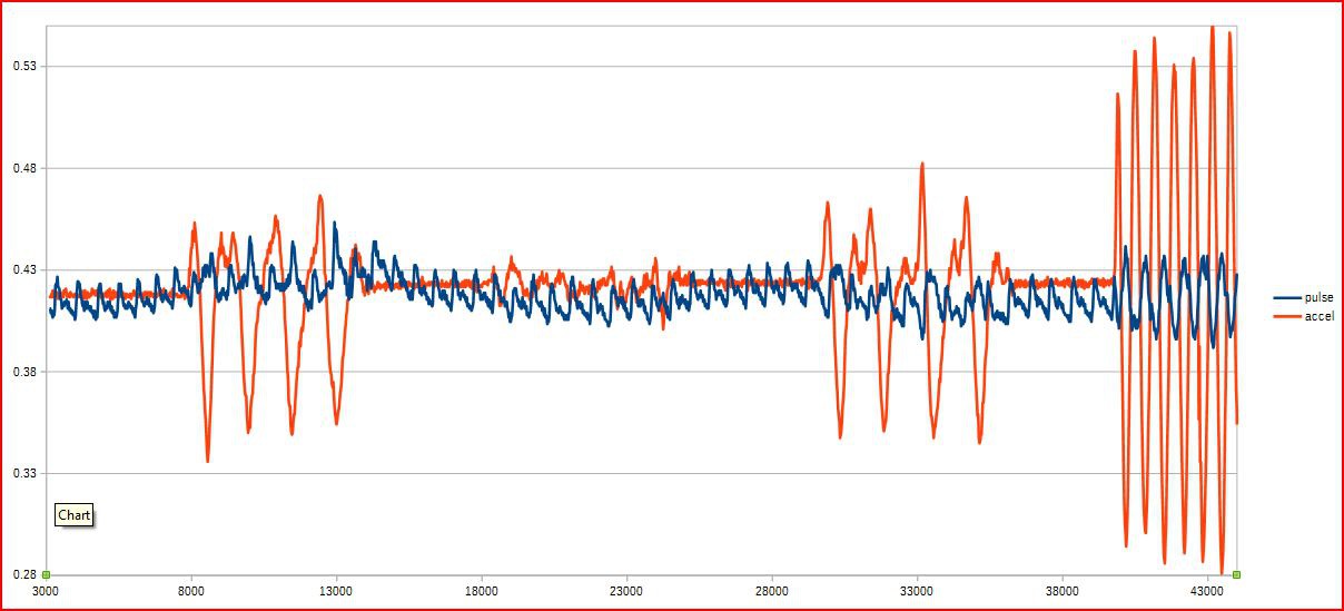
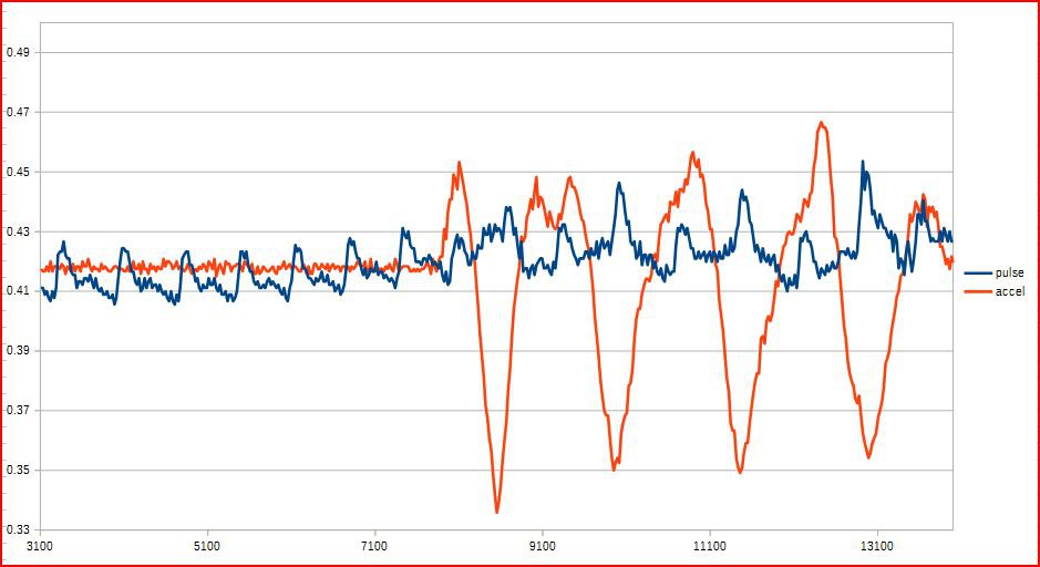
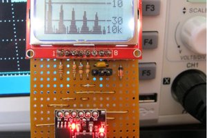
Being able to non-invasively monitoring heart rate is pretty standard these days. The dominant technique is photoplethysmography and is performed by shining a light through the finger and and detecting the transmitted light with a photodetector. The amount of the light transmitted is proportional to the amount of blood in the arteries which changes with flow of blood through the arteries. By graphing this relationship, we can detect heart rate. But, being able to do this continuously, while the person is moving and active is a little bit difficult. Companies like Mio with their ALPHA have had some success doing this. I am trying to emulate Mio's technique by using an accelerometer to detect movement and therefore cancel noise in the pulse signal due to movement.
 agp.cooper
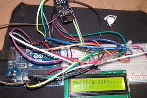
 electronicsworkshops
 Guillermo Perez Guillen
 Capt. Flatus O'Flaherty ☠