 fl@C@
fl@C@Ok.. so I have been spending a LOT of time getting this process hammered out... and tweaking my shapeoko2 to do it, etc.. Not to mention I just bought the shapeoko and had to build it and get it working.. lol.. Maybe I'll make a writeup for the special case I made for the power supplies and everything.. I tricked it out pretty well, with a TFT display and a microcontroller just for handling everything including the laser/spindle pwm, etc...
Anyway... Here's where I'm at mostly...in pictures...
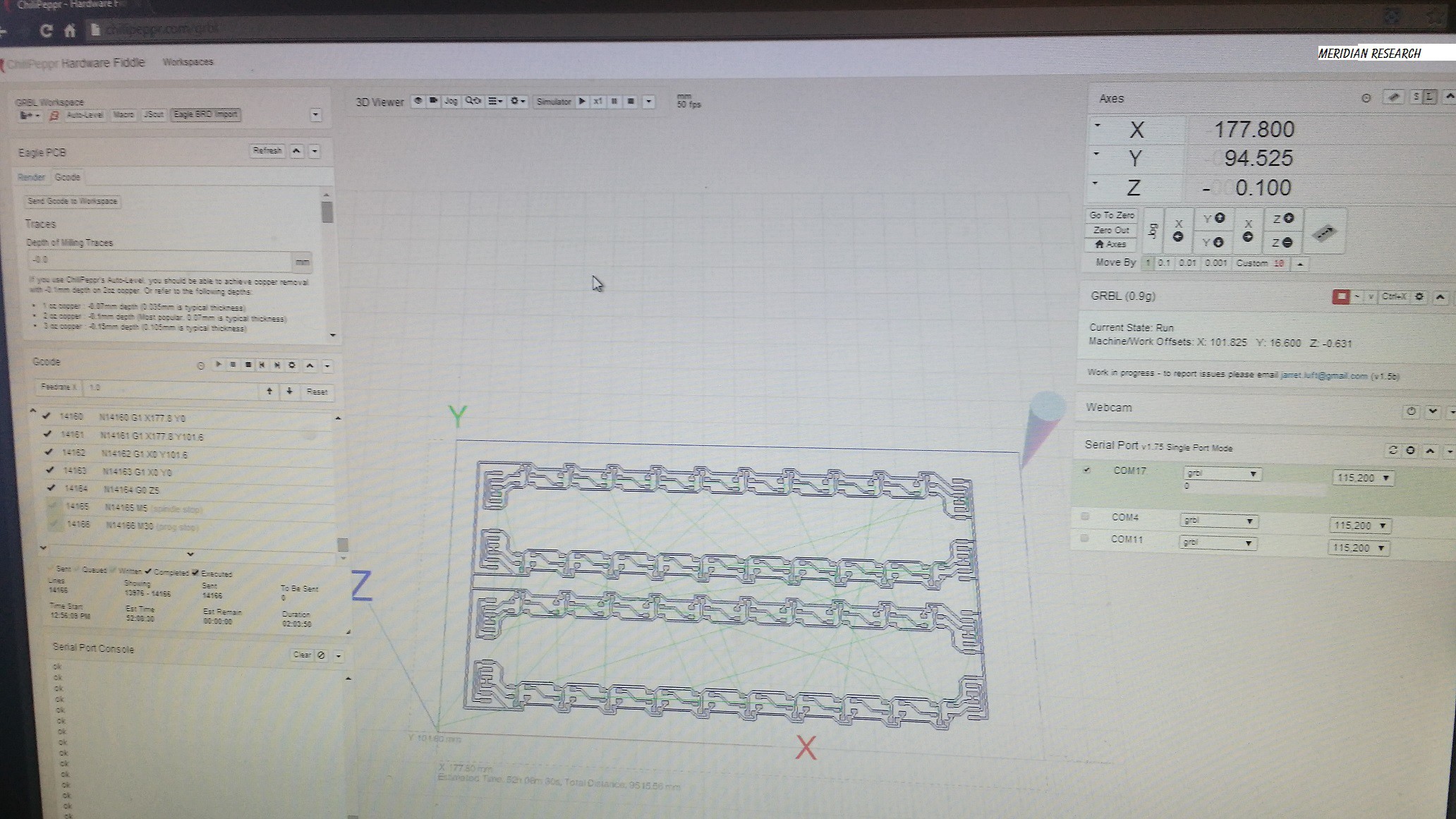
A board that was exported to gcode from eagle with pcb2gcode.... loading into chilipeppr.com...
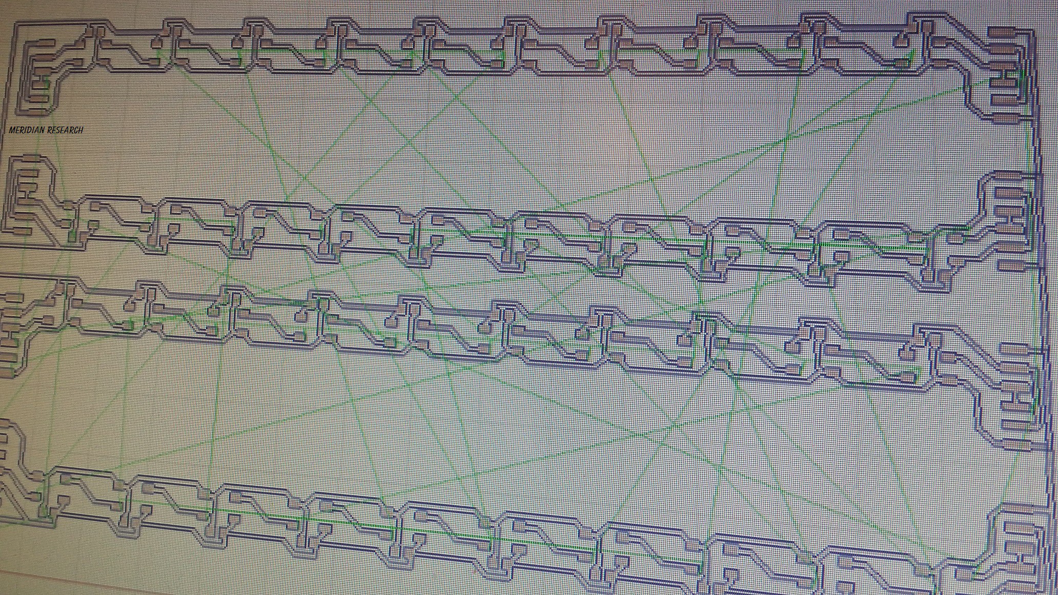
closer...
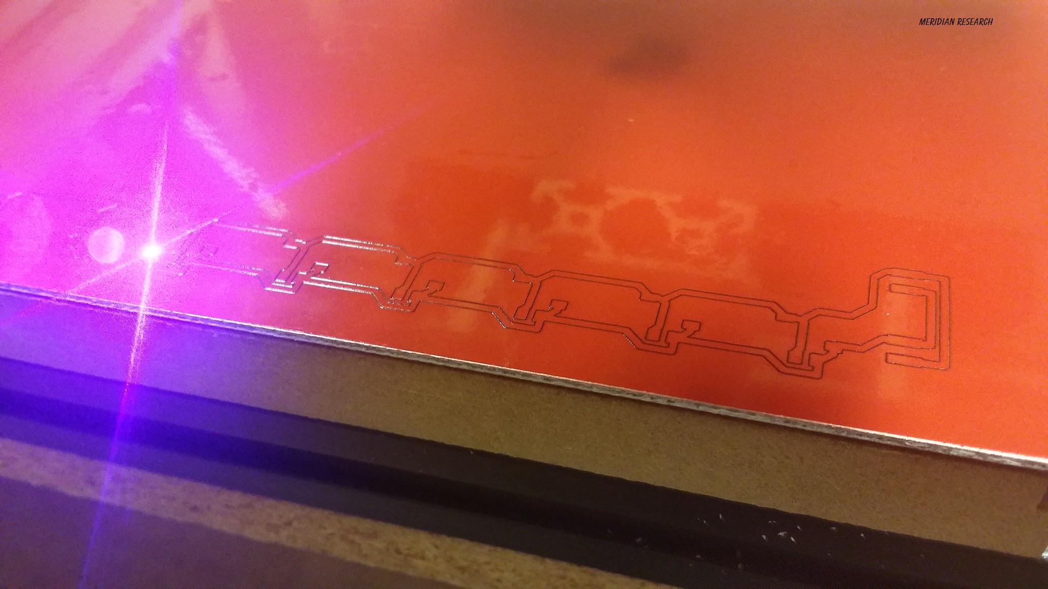
A pcb in the shapeoko2 with the laser going to town on it... (don't do this at home... vinyl produces nasty chemicals while being cut... you might get sick or worse.. it's not my fault if you do this in a non ventilated area and so on..)
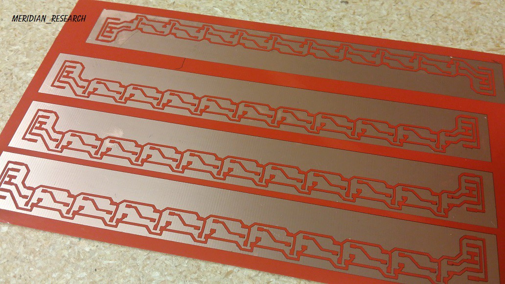
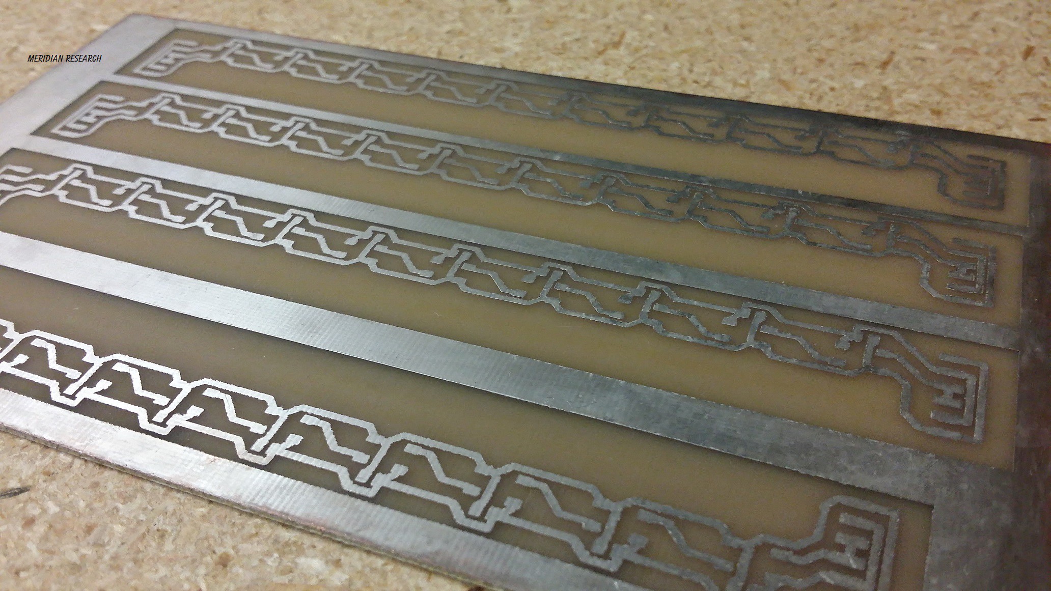
The board after the laser has made its cut..
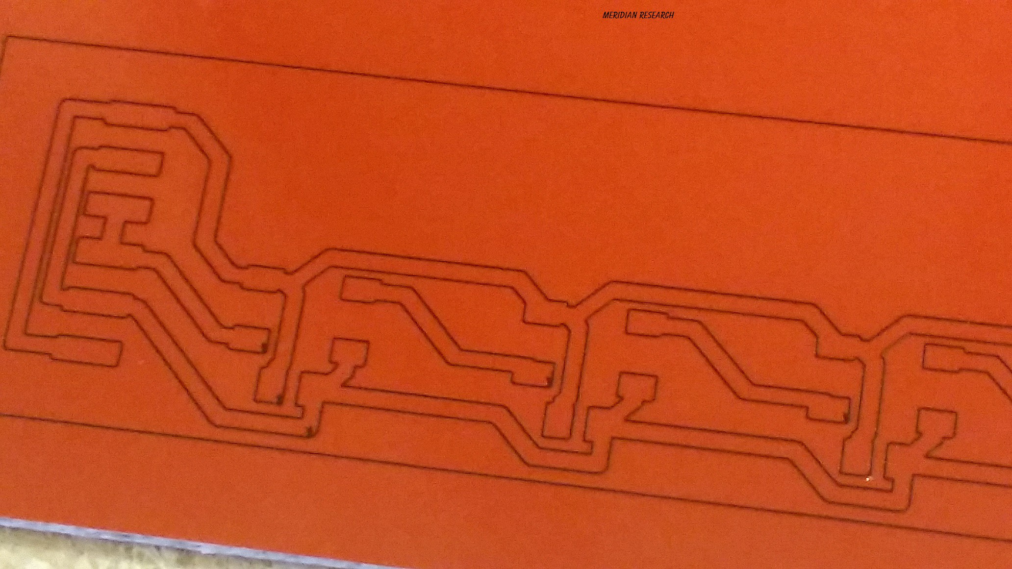
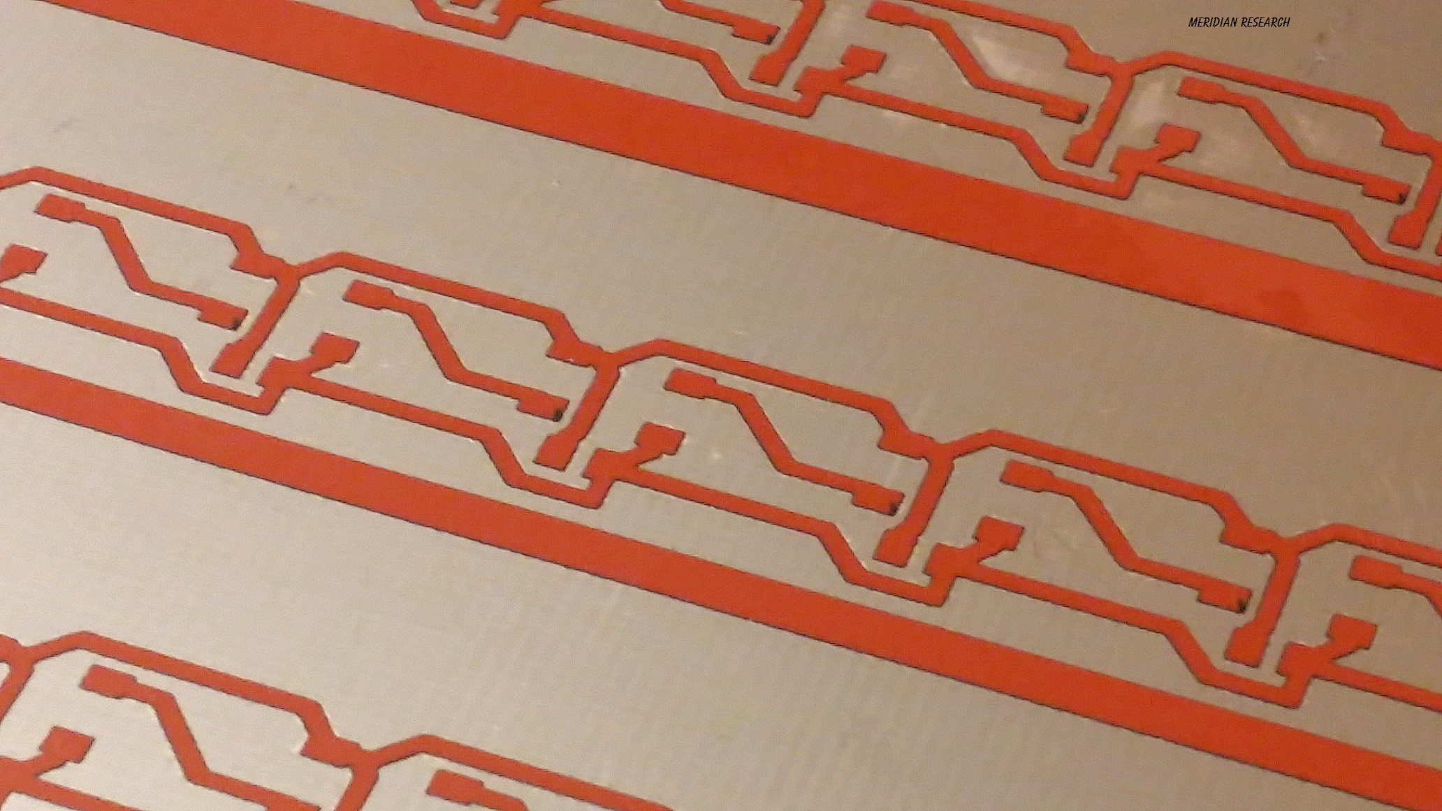
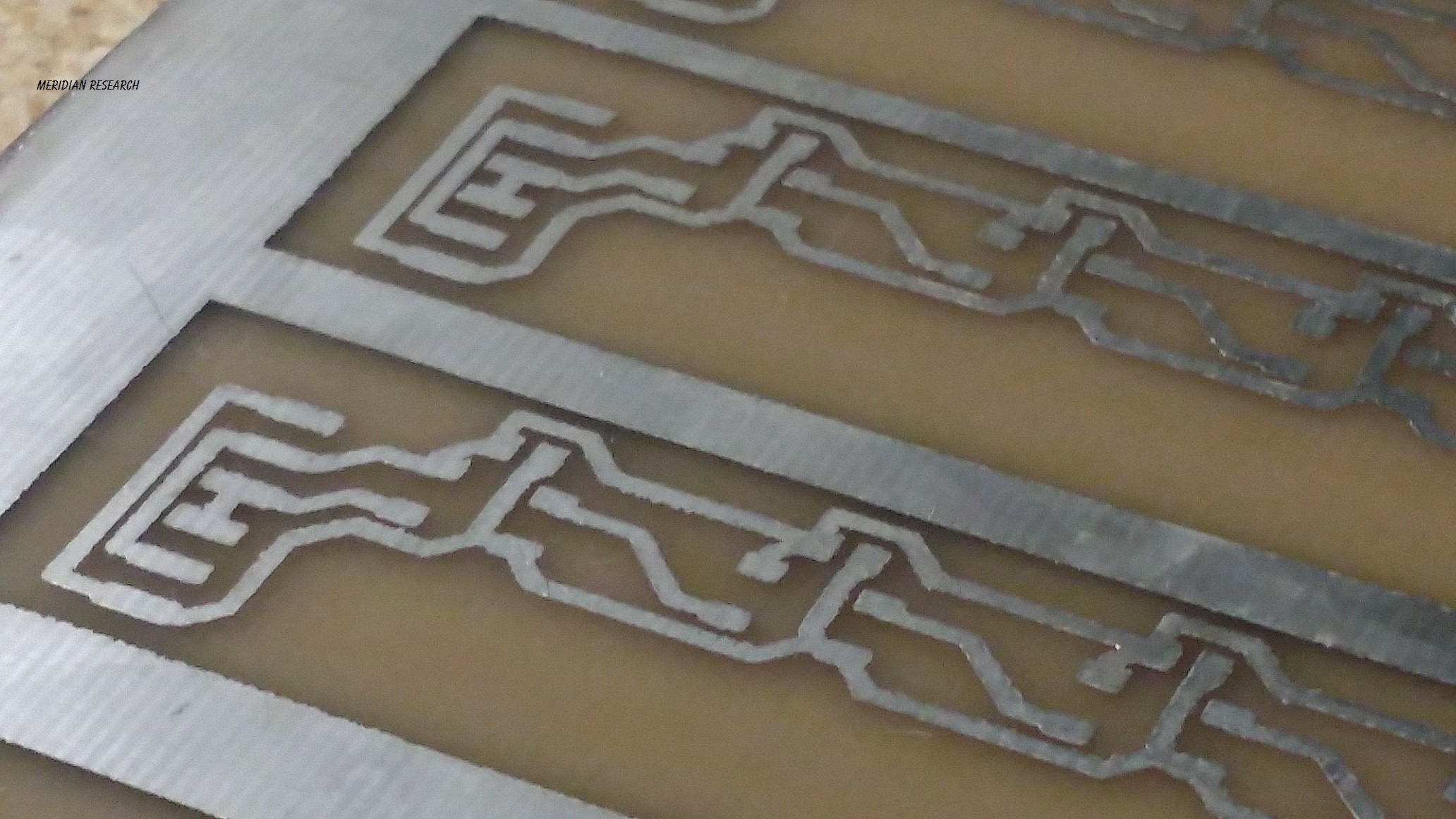
The board after you've peeled back the parts you don't want...
closer....
The same board after being etched.... (I'm not good at this yet... haha... and I want to switch from ferric chloride to h2o2 and muriatic acid soon)
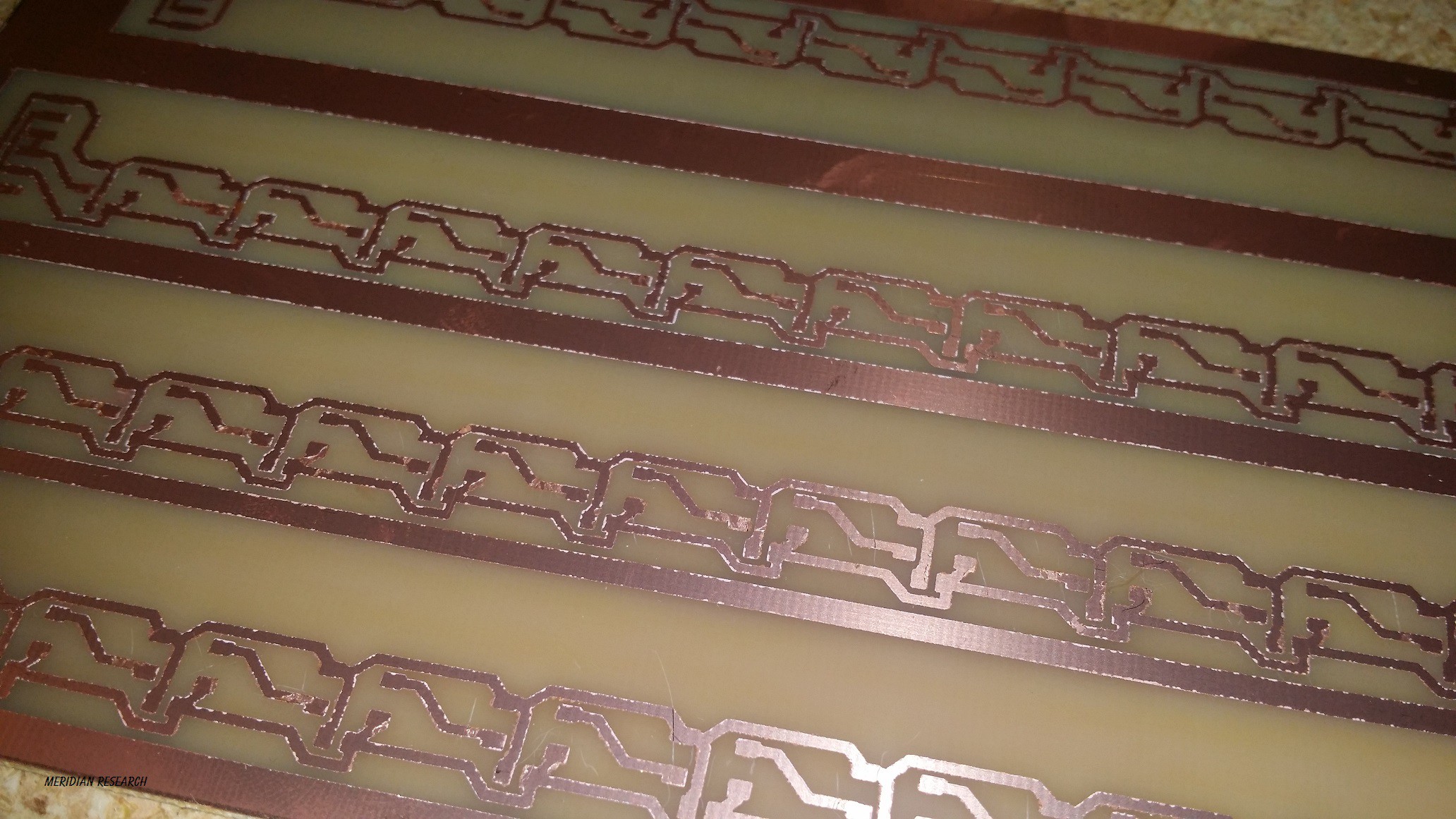
The same board again but plated...
closer....
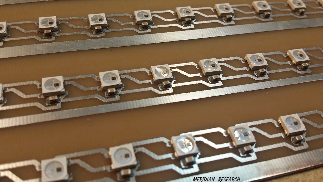
And now being reflowed with the LEDs on it.... (This is just a test board... )

And a closeup after being reflowed... :)
And.... powered up connect to a micro....!
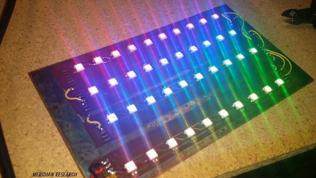
Works great..! =D
Discussions
Become a Hackaday.io Member
Create an account to leave a comment. Already have an account? Log In.
I'm guessing you want to actually generate paths that are either inflated or deflated. You should be able to do that by entering a negative value in the path inflation. Yeah, the settings maybe would be better in a larger modal dialog box. No settings storage has been created yet, so that's good feedback. You can always fork it and tweak, but it's early days for this new feature in ChiliPeppr so always looking for good feedback. I find pcb2gcode to be hard to use and always have. I also have found that it just stopped working in newer versions of Eagle, so that was one of the reasons to make a new feature in CP.
Are you sure? yes | no
Hi John,
I will definitely try playing around more with the negative value in the inflation when I try the TQFP32 soon.. For now, when I use a negative on the pads to try and get a little space between it separates the pad from the trace.. http://imgur.com/tPpAnq4 I know making the pads smaller isn't all that's desired, but it would be nice if it didn't cut them..
My ultimate goal is to use the process documented in this project for one off boards that I don't need to make a lot of, or that I want to produce quickly and easily.. And for boards that I want to make a lot more of, I want to use the process I am documenting in the http://hackaday.io/project/4565-tonerless-pcb-templates-for-uv-exposure and http://hackaday.io/project/3787-diy-uv-exposure-oven-for-pcb-etching-and-masks projects..
There's a slight difference in requirements... for larger parts, it doesn't seem to be too picky..but when I try to do something like TQFP32 the gaps between pads gets touchy.. which is why I tried a negative on them...
I'll totally be sold on skipping pcb2gcode if the chilipeppr import would do both sides a of pcb too..unless I'm confused on how to use it...I haven't been able to get it to do the bottom side (or mirroring - x or y ).. Or layering in general for that matter... I would LOVE to see a selection for layers.... cutting templates for the silkscreen or solder mask would be AWESOME.. =D An export of the gcode would be a nicety too!
Edit: Almost forgot it'd be great to be able to set the origin point after importing also!
Edit2: I had the 'clip wires' checkbox set..!! Oops..my mistake!!! So nevermind on the comment and pic above!! =D
Are you sure? yes | no
I'm gonna go ahead and reply again.. :D So, I've played around more.... and I'm sold.. After tweaking some settings... (the negative numbers work great..don't know why I didn't try that before!) I don't see a reason for pcb2gcode anymore....with a tiny exception.. Since I am using a laser.... I have the TTL line connected to the D12 - Spindle ON/OFF pin..which works great if I send the M3 or M5 command... Is there any possible way to tweak Chilipeppr to send the M3 - M5 commands instead (or in addition to) the Z axis move?? Or if not, is there a way to export the gcode after you've done the eagle import, etc?? Currently, the only way I've gotten anything to work without cutting across everything with the laser when it moves to a new point is the set the Z axis to raise far enough and xy to move fast enough that the laser is out of focus and won't cut very well... not very elegant.. ;( This single feature would make all this work flawlessly... :D
Are you sure? yes | no
Have you tried using ChiliPeppr's new Eagle BRD import directly where you just drag in the BRD file rather than having to use pcb2gcode?
Are you sure? yes | no
I have.. I think it's tailored very well for milling pcbs... I haven't been able to get the same quality from it as I have from pcb2gcode using a laser... I'll publish the settings I use on pcb2gcode to get a fine enough pitch to do a tqfp32 pretty well.. I really should spend some more time with Chilipeppr's import... I think part of my preference is the interface is easier to see all of the settings at once with pcb2gcode, and I'm not sure I've figured out how to save my settings with Chilipeppr... I'll also post a little about the configuration on my shapeoko to do this well...
Are you sure? yes | no