 Kevin H. Patterson
So, the PowerEdge R820 has a PCIe x16 slot, but there is no auxiliary power cable for graphics cards that require one, and no place to plug in such a cable either. At first glance, it also does not appear that there is any convenient place to tap +12V power within the system.
However, along the front edge of the motherboard (behind the front drive bays) are a set of 6 connectors for the drive bay backplane. 3 of the connectors are for backplane control signals, and the other 3 are for backplane power. On my system, only 2 of the control and 2 of the power connectors are used. The rightmost power connector, labelled "BP3" is available.
The backplane power connectors are 8-pin Molex 43025 series connectors. By visually inspecting the cables going to BP1 and BP2, and using a voltmeter, I was able to identify 3 ground pins and 3 +12V pins. (The remaining two pins are both gray wires on the BP1 and BP2 cables. One of them reads +3.3V and the other nothing. I am guessing that the extra gray wire is a 3.3V sense signal. I just left both pin locations unpopulated where gray wires were.)
The mating plug that fits the motherboard backplane power connectors is Molex part #43025-0800. The insert pins for the plug are Molex part #43030-0001. You can use the official crimp tool or you can try to do it by hand. I soldered my wires into the pins, but you have to be careful not to use wire or extra solder that is too large to fit the pin into the connector afterward. Bought these parts from Mouser.
For the cable, I used an spare PCIe auxiliary power cable that came with a PC power supply that has detachable cables. After my assembly with the connectors, the cable is exactly 20.75 inches long between the connectors. This is perfect for my setup. If your graphics card is a little shorter or the PCIe auxiliary power connector is in a different location, you may need a slightly longer cable. But don't make it too long because there isn't a lot of room to stuff any excess.
A photo of the pinout diagram is in the gallery. Study it carefully. The diagram shows the pin functions looking into the end of the BP3 connector on the motherboard. Double-check everything with a voltmeter before frying your server or GPU.
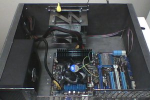
The AMD FirePro W7000 graphics card I used was a decent workstation card that I had lying around. It barely fits in this slot. Originally it had a metal RAM heatsink that extended from the bottom side of the card, making the card much longer, but I removed it. Just be sure to put the screws back in the card to hold the top side heatsink / fan assembly on securely. :) I don't think the RAM really needs a huge heatsink, and there is plenty of cool airflow in this server. No problems so far...
The back edge of the GPU card comes right up to the top CPU daughterboard, and the edge of the PCB rests directly on top of a metal bracket near the rightmost RAM slots. There is a PCB trace on the bottom of the GPU right along this edge, so I covered it with a strip of electrical tape just so it doesn't wear thru and short out agains this metal frame.
There is very little clearance above the top the of the GPU for air intake into its cooling fan. With forced airflow through the server, I don't think we need a lot, but I put a little rubber foot on the top corner of the GPU card near the PCIe auxiliary power connector, just to gently push the card down when the top cover of the server is installed and create a little gap where air can get sucked in to the fan. The foot is about 3/16" thick. I then decided to put a dab of lithium grease on top of the foot, to lubricate it a bit as it was extremely difficult to slide the top cover off again, sliding against the rubber. Now it's ok.
The auxiliary power cable was bent down and to the right, under the card, and routed back along the top right edge of the server. There is a space...
Read more »


 Jake
Jake
 Marsupilami
 cprossu
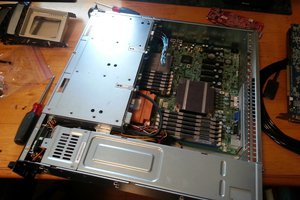
 Michael Murillo
Hi Kevin, nice project. I also have got a R820 with 16 SAS drives. On its own the server run fairly quiet. When I plugin an extra video card (no extra power required) and the R820 performs a power characterization the noise level is up by 2.5 or so. I wonder does this also happen with your setup and with extra power cable? What OS are you running your server on?
Thanks and regards.