The ATtiny is the brain of the system. I can actually use a ATtiny85V if I need more space.
The microcontroller is almost always sleeping. The RTC is keeping the current date and time using about 250 nA (yes, it's nanoamperes). I use the internal clock to save power and pins. When I need a delay, I reduce the clock speed to further save power!
The RTC chip is really tiny! There is a pad every 0.5 mm. If you look carefully, you will see that I damaged some unused pads during the soldering operation, next time I should attach a dummy track so that the pad is better held in place.
LEDs are controled using charlyplexing. This technique allows to control up to 12 LEDs with only 4 pins.
The ATtiny is programmed using AVR ISP the first time, then a I2C bootloader is used as I need to free more pins!
I2C is also used to comunicate with the RTC. One side benefit is that I can access the RTC directly using my programmation port.
The programmation port is done using a piece of PCB which is inserted in the battery holder. There are additionnal contacts under the battery to make the connection. To ensure good contacts, I need some kind of springs. Next time I think I will change this for pogo pins contacts which should be more reliables.
The switch and the RTC interrupt are connected to a pin used to drive LEDs throught a resistor. When the button is pressed, there is actually some LEDs which can not be driven. The code piloting LEDs stops automatically when it detects this situation.
 Simon
Simon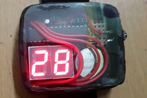
 Brainy.Baboon