 Audrey Robinel
Unlike my previous robot, whose chassis where simply a wooden plate approximately cut and drilled, i decided to construct the chassis only after thoroughly designing it. I thus searched an open source 3D modelling soft, and happened to really enjoy OpenScad. This software enables the user to program rather than click, constructing 3D shapes by combining and altering primitives volumes. Using this, i designed my chassis plates in a parametric way.
First of all, i defined all constraints, such as the motors screw holes diameter, position relative to the edge, distance between front and back wheels (i decided to use 4 wheels, with two motorized ones, and tracks). All those parameters are fixed due to the parts that i chose to use.
I thus have a fixed robot length, but the width can be set by the user (the length can too, but by setting the distance between front and rear wheels, and motor parameters, not directly, although i may include a variable to increase the length).
At this point, we have the base dimensions for the base plate. A second layer is automatically defined, depending on the size of the first layer, but larger (top layer width=bottom layer width + 2* tracks width) and longer.
The first layer contains the lipo battery, a sensor, the charge circuit for the battery, and a small circuit area, with the motor driver and the switching regulators.
I calculated the ideal motor screw holes positions, depending on the Pololu specifications for my motors (micro metal gearmotors) and fixations. In order to be able to use 2 or 4 motors, the same holes are present in the back and in the front. We will figure later how to attach the free-spinning wheels. The motors can be either in the front or the back.
In this version, the motors will be on the underside of the level 1 plate, so i added rectangular cuts in the chassis near the motors to pass the cables. The top layer have the same cuts so that cables can be run from one to another layer.
Here is a projection in 2D :
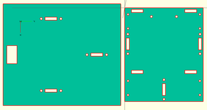
On the left, the top plate, on the right, the bottom plate, rotated by 90°.
You can also download the DXF file of the chassis, including those two plates.
If you want to modify the file, you can download the scad file for openscad with the full robot, or the scad file with the projection in order to obtain the 2D dxf file.
It can either be laser cut (perhaps with a CNC?), or simply printed, then using a jigsaw you can cut the plates, and drill the screw holes, and motor wires cuts (obciously not a nice rectangle, but some round holes will do).
The code is commented (in english), so one should be able to adapt easily the dimensions.
Please note that this isn't the final version, as i see some adjustments that i'll probably made for the next revision. In order to connect the top and the bottom layer, we will have to design something 3D-printable.
See you in the next update!
Discussions
Become a Hackaday.io Member
Create an account to leave a comment. Already have an account? Log In.