 Audrey Robinel
 As seen in a previous project log, i have two plates for this robot. The lower one sports the battery, charge circuit, power regulator, motors, ultrasonic sensor and the motor driver.
The top plate supports the "brains" of the robot, i.e. command electronics. This means a Raspberry pi, an Arduino uno (for now, later it will be a a more compact Arduino compatible circuit, once i design it and have everything i decide what i want to include on it). More sensors are to be included, such as a camera module for the raspberry pi, along with a servomotor to orientate it.
As of now, i also have micro switches to detect collisions, and some room for a half size breadboard.
The question here was how to connect the two stages, and pass cables from one to the other. I decided to design a support structure specially for that. Since a plane needs three points to be defined, i chose to use three support structures. Those beams had to be strong enough to provide stability to the top plate, while being simple to print, identical, with the ability to pass cables through it. Here is what i designed :
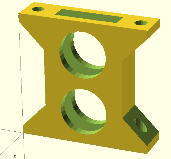
This beam is symmetric so that the up and bottom are identical, left and right and front and back also, making it easy to mount, since you just put it where it goes, with no worry about orientation. If it screws, it is how it should go.
Globally, it is a hollow box, with 2mm thick walls. I cut two holes to not only save material and print time, but also to pass cables. The rectangular opening that goes from top to bottom serves the same purpose.
Indeed, some cables have to come from the underside of the robot, to the top of the bottom plate, and other cables goes from the top ob the bottom plate to the top of the top plate through those beams. Female and male jumper wire fits in, however, in the next version, i will make the beam slightly higher, and the round holes a bit more elliptic to facilitate the insertion of the connectors of the jumper wires.
For this robot, three of these beams have to be printed :
You can also follow this link that leads to a larger version of this picture, on my wiki.
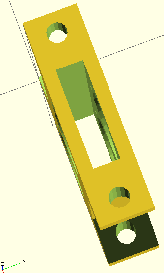
The piece has two foots on top and on the bottom, with 3 mm diameter holes, for screwing this to the plates. It works perfectly with M3 machine screws, without a nut.
Once installed, this is how it looks :
 Of course, the chassis plate have been designed to work with those beams, as not only the screw holes are present, but rectangular cuts on top and bottom, aligned so that this positions the top plate adequately in relation to the bottom plate.
Here is thescad file to download if you want to adjust the beam (walls thickness, height, etc), andhere is the stl file i used for those prints, with a beam height of 35mm, ready to print.
I printed those in PLA on my printrbot simple metal at fast speed, in 0.3mm layers, with no problems :
 I could have printed it nicer, but it does the job perfectly as is.
It used 1200mm of filament per beam, for an individual print time of 30 minutes.
See you next!
Discussions
Become a Hackaday.io Member
Create an account to leave a comment. Already have an account? Log In.