 Christoph
Wanting to switch a higher voltage of 100-200 V requires you to carefully read the datasheets of your electical components. Most general purpose devices are only suitable for voltages below 60V or less. Especially for Nixies there are commonly used driver ICs K155ID1 (74141) available. They are old (production stopped long time ago). Do you really want to by old ICs from Ebay, not knowing if they're still ok for a rather high price? I don't think so since you can easyl build it yourself. Take a Transistor like the following, hook it up to a microcontroller (or shift register if you want to save pins) and you're done.
The MPSA 42 is a very (extremely) cheap, known available NPN High Voltage Transisitor with a max. Collector-Emitter Voltage of 300V. Of course there are many FETs available, but I could not find one as small, cheap and common as the MPSA 42. Pricing of 4(Euro)Cents per Piece for a MPSA 42 vs. 50(Euro)Cents and more per FET. What would you choose?
At some point you want to think about decoubling a 200V circuit from your tenderly beloved microcontroller. I leave it up to you to think about why you should or should not considere this.
This lead to the problem of safely switching the MPSA 42 with a common optocoupler CNY17F4 (or similar). I do not know if there are any optocouplers with voltage ratings like the MPSA 42. If yes this can be obviously simplified however I wanted to go with what I have available. Problem is, the CNY17F4 has max. Collector-Emmiter Voltage of 70V.
Long speach, easy circuit. Here my simple suggestion:
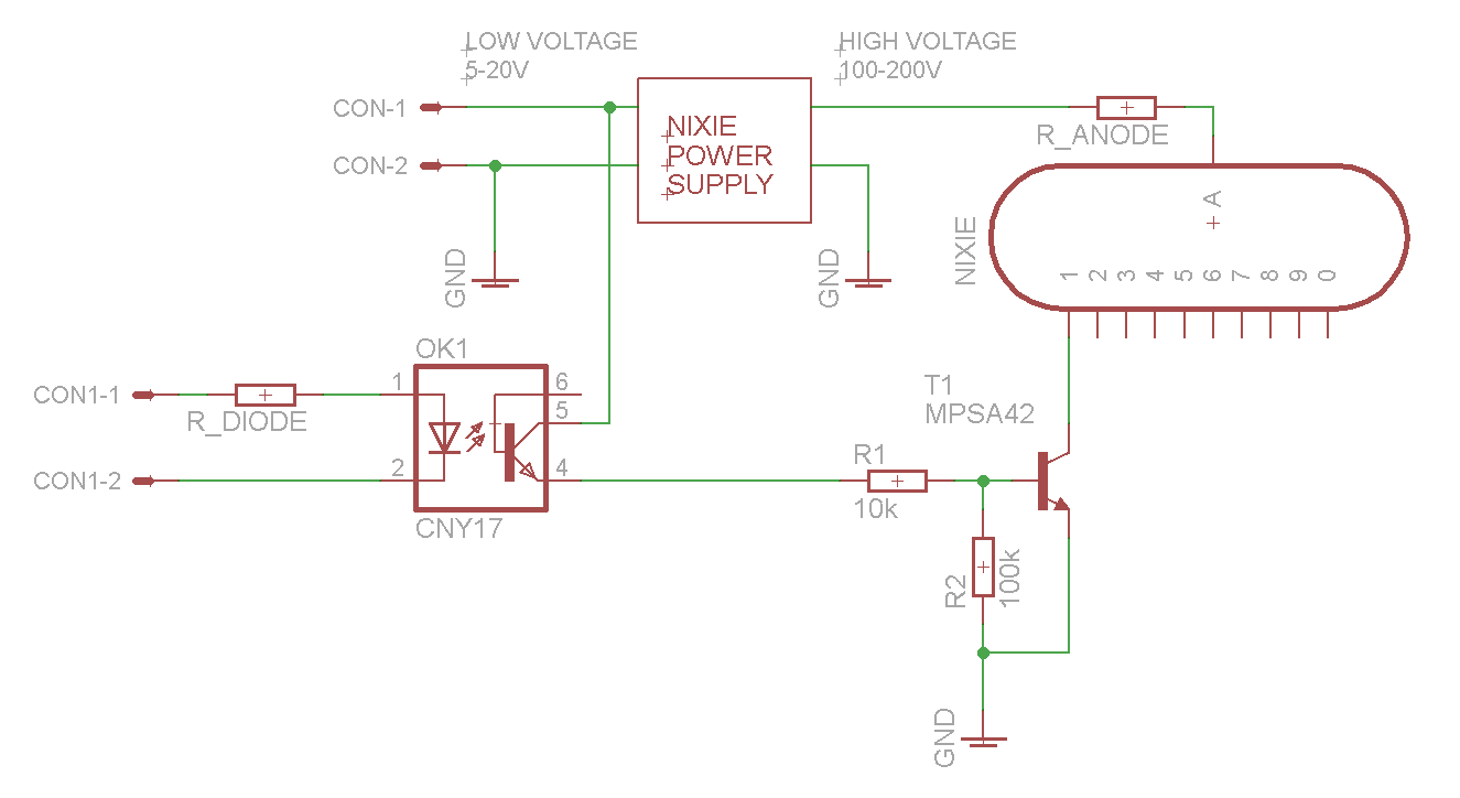
Since there is a suitable lower voltage available for the stepup-converter I use it to supply the secondary side of the optocoupler OK1. If thats not possible you have to find an additional voltage supply. You might think about using a Zener-Diode on the High-Voltage Side. Keep your current consumption in mind which might be too much for the High Voltage Supply.
OK1 is switched on by an external supply (coming from a uC or whatever). When switched on it switches T1 in a conducting state. R1 and R2 are to ensure safe switching states. T1 is tied to ground (R2) when OK1 is off. R1 is the Base-Resisitor when OK1 is switched on. Keep in mind that R1 and R2 are a Voltage Devider. The ratio R2/R1 should be rather high. 10 in my case.
That's it. You can easily adopt this scheme for any other load you want to switch with a galvanic insulation.

 Azri Jamil
 mircemk
 Tijl Schepens
 Albert van Dalen
Nixie drivers do not need to switch the supply voltage. an 80V npn works fine. One nixie segment is always on, so it is only the on voltage, not the supply voltage.
Also the transistors voltage is the VCB-base shorted to emitter spec, not the VCBO (base open spec)