 willbaden
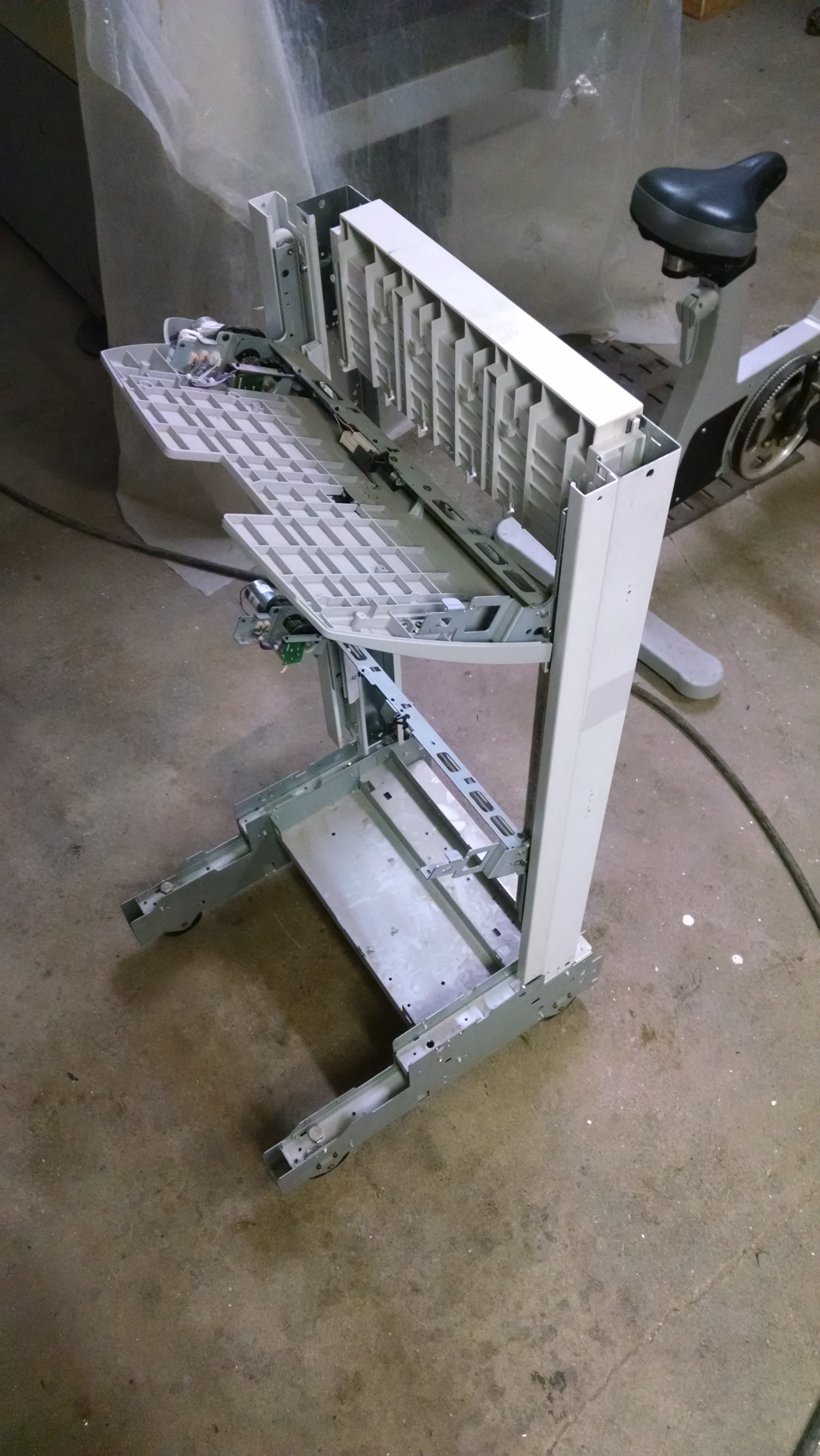
The Z axis uses a tray selection option that was available for printers. It has two tray selection devices that could select where which slot the papers came out of. It uses two rack and pinions, one located on each upright. The location of the uprights was towards the center of the bottom cart.
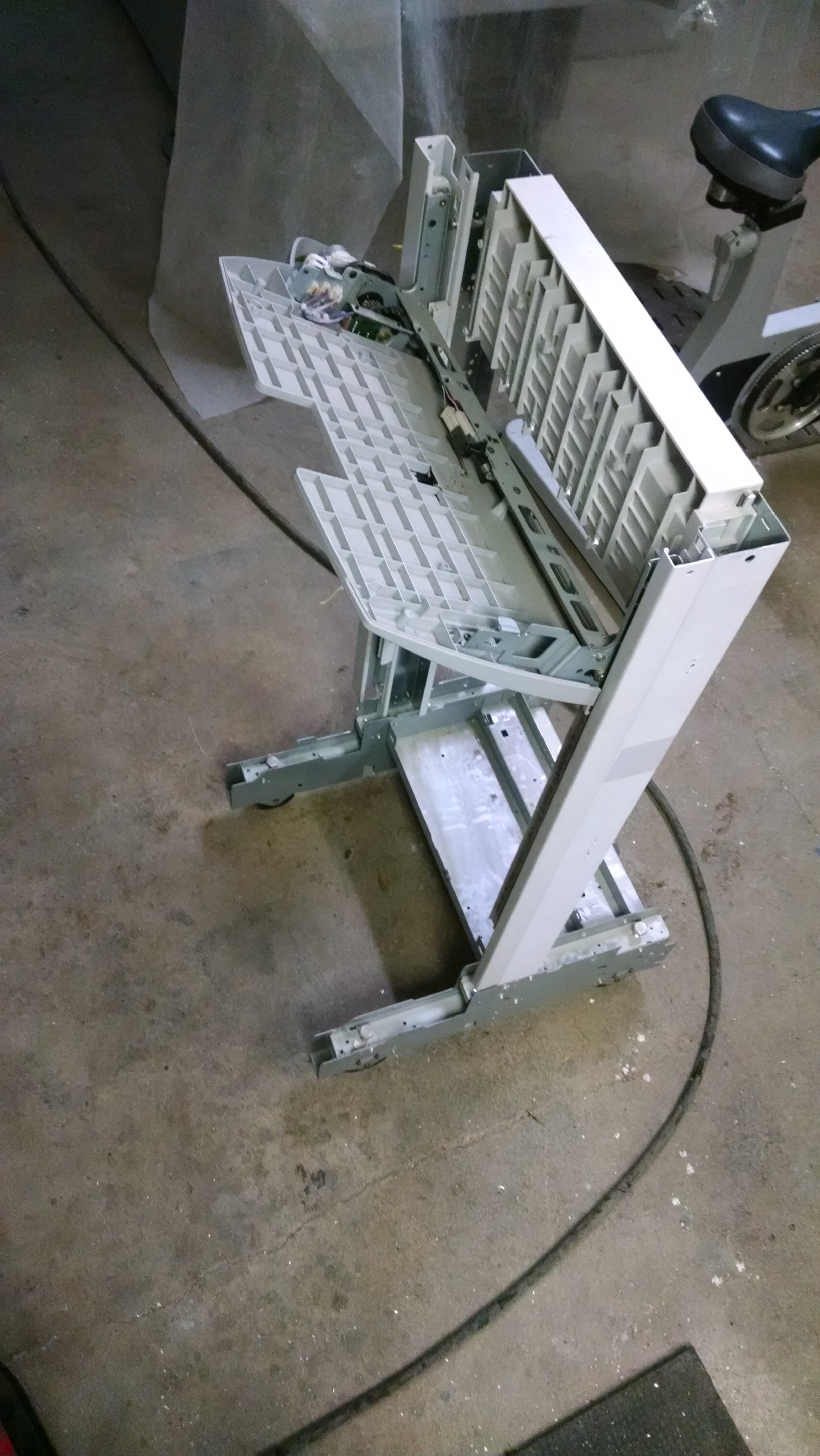
This was shifted towards what is now considered to be the back of the cart.
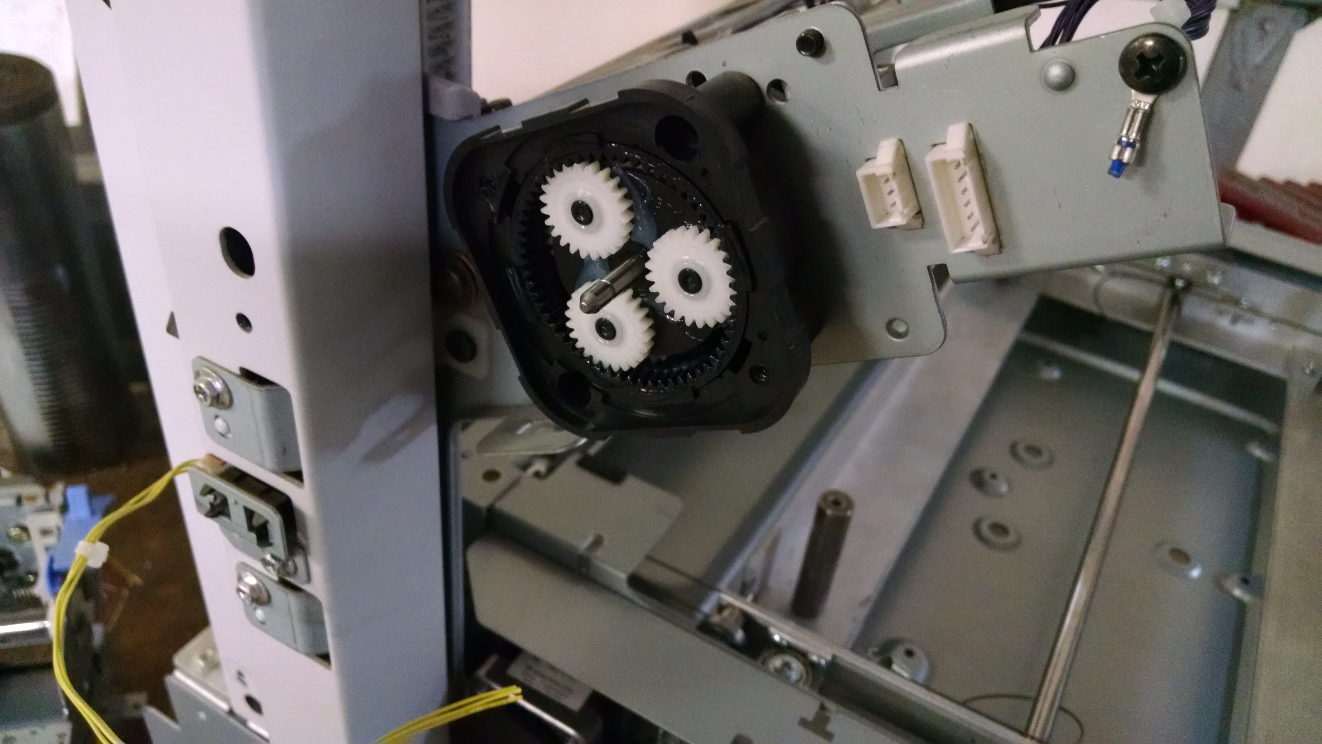
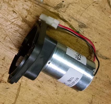
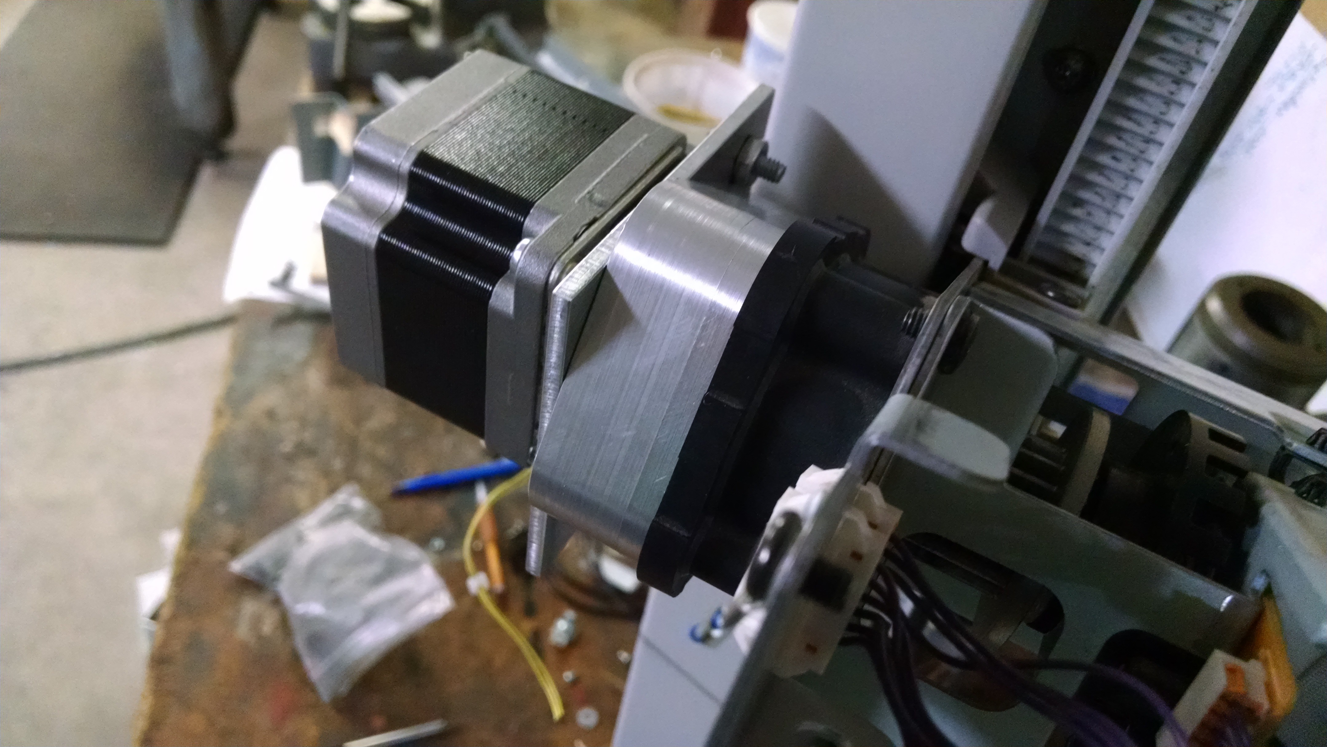
The motors that were mounted to the tray selectors were DC motors. Instead of reusing them, stepper motors will be used. To mount them took a little bit of work. The gearbox is a planetary gearbox. This will allow or some good torque and the cogging of the stepper motor will keep the z axis in one location even if power is taken away from it.
The original plan was to use the old dc motor mount, but the holes for adapting the motor weren't lining up as well as I had hoped.
Instead a new aluminum cover was milled out from some scrap aluminum. Using CamBam to create the G code made life a little easier. The part was squared up with .020" per side oversize. This allowed for some cleanup and can be seen on the first side after being machined.

Notice the square bottom. This was the part that was squared up and gave the vise something easy to hold onto. The holes that needed locating were just center drilled to allow for a drill operation on a drill press. The second side was then machined. This side just needed the 3 holes for the adapter plate located, the face machined flat and the outside profiled. If one would look at the lower half of the outside of the part, it can be seen that the top and bottom did not match up perfectly.
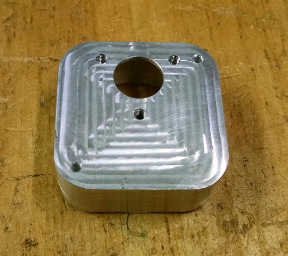
And here is a view of the completed part. The center hole is used as a bearing for the center gear of the planetary gears. This bushing was from the idler shaft that was used in the DC motor design. It was pressed into the center of the housing and drilled out just large enough for the shaft to ride in.

This was then mounted to the planetary gearbox.
 Between the housing and the stepper motor, an adapter plate was required. This allowed for a larger motor mounting bolt hole pattern. Not as good looking as the housing but it got the job down with a few speed holes.

Prior to mounting the stepper motor to the plate, the gear that engages the center planetary gear needed to have extra material added to it to allow for a setscrew to be used. Along with the set screw, the gear also had a slight press fit onto the shaft of the stepper.
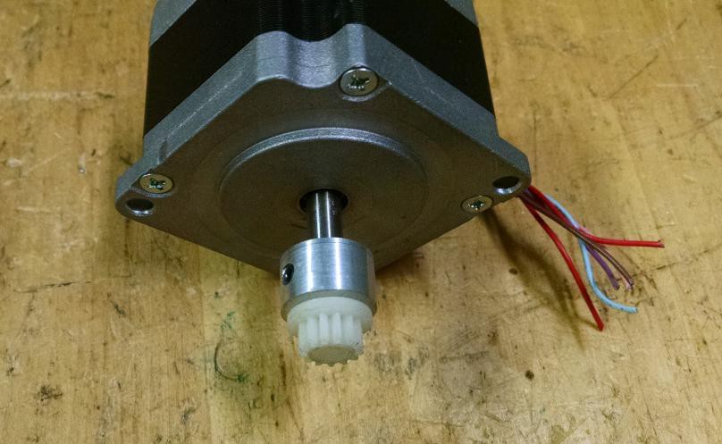
The motor was then attached to the planetary gear.
The next step is to test the z axis and verify operation. The plan is to use a simple UNO program that can send a variety of speeds and duration to the motor. This will be a different way to test the axis compared to the Y axis test that used Repetier Host for the testing.
Discussions
Become a Hackaday.io Member
Create an account to leave a comment. Already have an account? Log In.