 willbaden
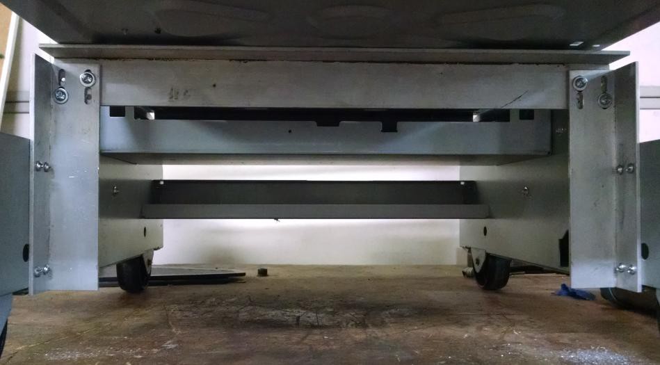
The Y axis has been finished to the point of being mounted onto the paper tray dispenser that will become the Z axis. The up and down movement of the Y axis is limited by the spring loaded shaft that runs along the X axis. The shaft shown in the middle of the picture below is spring loaded with a bearing attached and will push up on the lip that the upper bearings ride on.
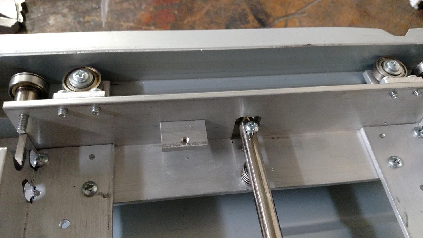
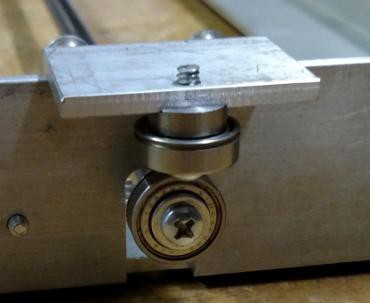
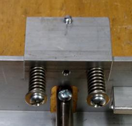
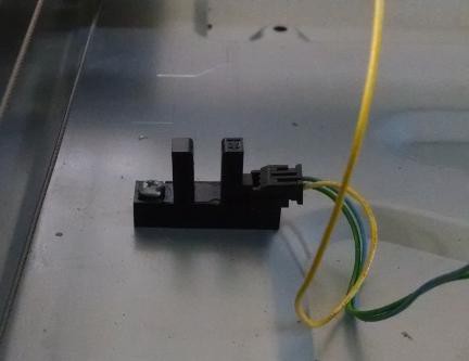
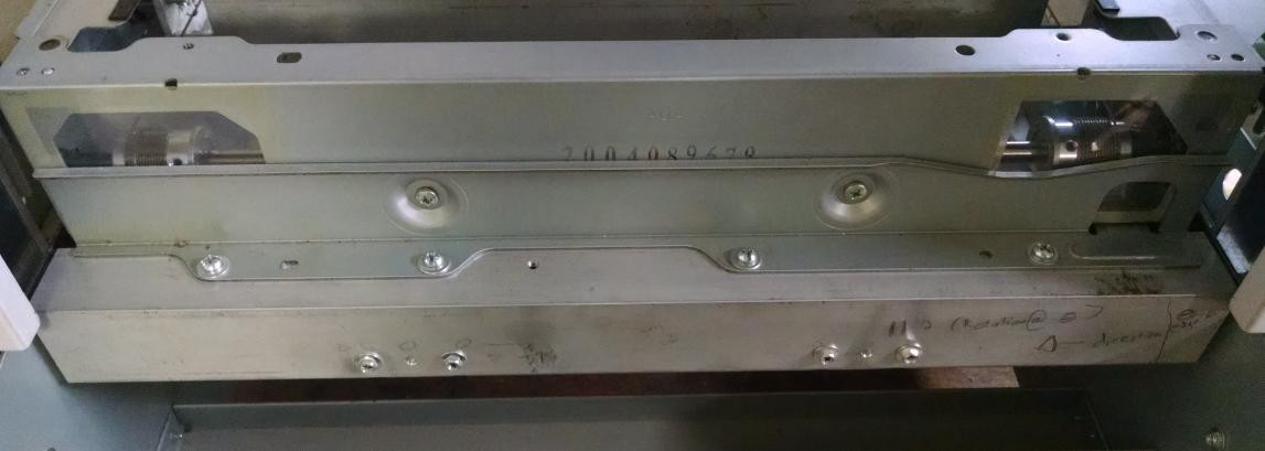
To keep the y axis located left and right, there is a single spring loaded bearing that pushes the two bearings on the other sides steel wall. (as seen in the picture above). Below is an outer view of the spring loaded left/right tensioner. Followed by an inside view showing the springs on the shafts that maintain the springs.
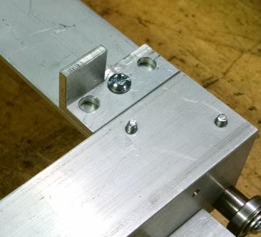
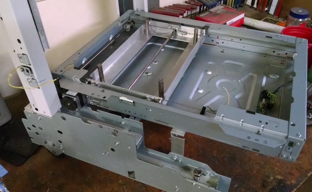
 And here is a 3/4 view of the completed Y axis mounting. In this picture, pay notice to the upright shafts that stick off of the bottom of the angles. These will eventually support the table.
Discussions
Become a Hackaday.io Member
Create an account to leave a comment. Already have an account? Log In.